98 Z3 2.8 Roadster

StephenK

Regular Member
British Zeds
Joined
Jul 24, 2024
Points
13
Location
South East England
Model of Z
Z3 2.8 Roadster Manual
Hello,
I have a 98 Z3 2.8 in Arctic Silver. I’ve never used a Forum before so a little unsure on the site navigation side. I have a very strange anomaly with my electric roof that I’m hoping to resolve.

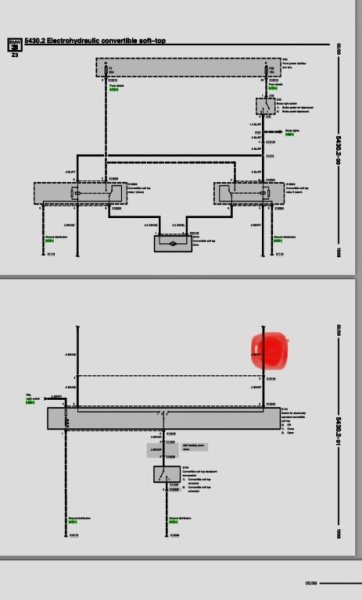
Quite confused and on the verge of losing my mind with my roof wiring. Maybe I need a fresh set of eyes to see what I’m missing. Brown and red wire between relay and switch had been cut by someone, close to the roof switch in centre console and an ignition live from radio wired into the switch there (marked with red dot). I cannot understand how this allows it to operate but it somehow does, with no need to have foot on brake to operate roof, in fact pressing brake pedal stops it from working. I disconnected the ignition live and ran a wire directly between relay to switch to bypass existing brown/red under the carpet which, as it should, has a live feed only with brake pressed but roof will not open with this correct wiring. In terms of the connector block at the motor/pump, I’ve got 12v at both red/yellow wires to relays. I have 12v blue/red from brake light switch when pressed and 12v from the wires from the relays brown/yellow, brown/red. Any suggestions would be gratefully received! IMG_7170.jpeg
 
Last edited:

RickyBobby

Zorg Guru (III)
Supporter
The M44 Massive
Joined
May 9, 2020
Points
143
Location
Sheffield, South Yorkshire
Model of Z
Z4MR
Unfortunately I can't help with your electrical query but hopefully someone who can will be along shortly - all I would say is that having owned several Z3's I've reached the conclusion that a manually operated roof is preferable to an electrically operated one. this is due to the plastic rear screen - although they often fold as they should sometimes they don't and if you don't perform the 'karate chop' maneuver you are likely to split the screen by folding it down. Irrespective of that if you don't apply suitable protection (BMW OEM towel or similar) the rear screen will get marked / scratched.

By the way, I assume you are Auto Knight from YouTube - I've subscribed to your channel and have been following your posts with interest so have attached a link below as I'm sure other forum members would be interested.

Auto Knight - YouTube
 

StephenK

Regular Member
British Zeds
Joined
Jul 24, 2024
Points
13
Location
South East England
Model of Z
Z3 2.8 Roadster Manual
Hello and thank you for your reply and for subscribing. Yes indeed, that’s me. I totally agree with you on the manual roof. In an ideal world it would be! I use a length of foam pipe lagging to ensure the plastic window folds correctly.
This electrical issue has been so frustrating as having studied the wiring diagram for what feels like hours, the reality of the wiring makes no sense.
 

RickyBobby

Zorg Guru (III)
Supporter
The M44 Massive
Joined
May 9, 2020
Points
143
Location
Sheffield, South Yorkshire
Model of Z
Z4MR
QUOTE="StephenK, post: 882237, member: 40337"]
Hello and thank you for your reply and for subscribing. Yes indeed, that’s me. I totally agree with you on the manual roof. In an ideal world it would be! I use a length of foam pipe lagging to ensure the plastic window folds correctly.
This electrical issue has been so frustrating as having studied the wiring diagram for what feels like hours, the reality of the wiring makes no sense.
[/QUOTE]

Glad to see you've found your way to the forum - it really is the ideal way to find the answer to any question or query relating to these cars.
And on that note hopefully someone will be along shortly to help :thumbsup:
 

Pingu

Zorg Guru (III)
3rd Party Trader
Joined
Dec 8, 2011
Points
145
With the wiring returned to normal, when you operate the roof to open, is Black / Blue at the pump = 12v ? You need to manually raise the front of the roof to electrically-close the micro-switch?
 

StephenK

Regular Member
British Zeds
Joined
Jul 24, 2024
Points
13
Location
South East England
Model of Z
Z3 2.8 Roadster Manual
I will check this when I have an assistant.
A couple of other points I forgot to mention in original post:
When I cut the brown/red wire at the pump unit, in order to attach the jumper wire, therefore providing continuity between dash switch and relay I had fully expected it to work as at that point it was wired correctly. As it didn’t work, I pushed that jumper wire into the connector of a known positive, the red/yellow. Despite having done this it would still only work when I reconnected the two ends of the brown/red wire that I had just cut at the pump end. I couldn’t understand how that could make a difference on the basis that it wasn’t connected at the dash switch end. This led me to believe that this brown/red wire might do more than just have a straight run from pump to switch, as indicated in the wiring diagram.
 

AntStark

Zorg Guru (III)
Supporter
British Zeds
Joined
May 15, 2021
Points
139
Location
Hampshire
Model of Z
2002 3.0 Sport
Great videos @StephenK ..keep them coming
I did laugh when you said “It’s a project not a money pit”..surely it’s the other way round 🤣
 

Jam03

Zorg Guru (III)
Supporter
British Zeds
Joined
Feb 21, 2022
Points
136
Location
Surrey
Model of Z
2.2i
Hi Auto Knight, love your YouTube content. You’re in the right place for advice here. Also, I suspect you are in Surrey, so hopefully will see you around at some point. We are lucky to have a resident local breaker of Z3’s in @spurs fan in a coupe who often has the bits you need when things break.

I have a manual roof and agree with @RickyBobby that in the interests of protecting the rear screen, you need to see how it’s folding and lay your protective material before you fold it down. The screen very easily kinks when folded.
 
Last edited:

StephenK

Regular Member
British Zeds
Joined
Jul 24, 2024
Points
13
Location
South East England
Model of Z
Z3 2.8 Roadster Manual
Hi Auto Knight, love your YouTube content. You’re in the right place for advice here. Also, I suspect you are in Surrey, so hopefully will see you around at some point. We are lucky to have a resident local breaker of Z3’s in @spurs fan in a coupe who often has the bits you need when things break.

I have a manual roof and agree with @RickyBobby that in the interests of protecting the rear screen, you need to see how it’s folding and lay your protective material before you fold it down. The screen very easily kinks when folded.
Thank you! Yep I’m not far from there and it’s good to know there’s a local breaker - extremely useful. It’s not often I find the need to ask for ideas but this damn roof has had me perplexed.
 

StephenK

Regular Member
British Zeds
Joined
Jul 24, 2024
Points
13
Location
South East England
Model of Z
Z3 2.8 Roadster Manual
Great videos @StephenK ..keep them coming
I did laugh when you said “It’s a project not a money pit”..surely it’s the other way round 🤣
I think it’s turned into both - a project and a money pit. It’s all good though, free and single so nothing else to spend my money on 🤣
 

AntStark

Zorg Guru (III)
Supporter
British Zeds
Joined
May 15, 2021
Points
139
Location
Hampshire
Model of Z
2002 3.0 Sport
What videos?
 

Pingu

Zorg Guru (III)
3rd Party Trader
Joined
Dec 8, 2011
Points
145
I will check this when I have an assistant.
A couple of other points I forgot to mention in original post:
When I cut the brown/red wire at the pump unit, in order to attach the jumper wire, therefore providing continuity between dash switch and relay I had fully expected it to work as at that point it was wired correctly. As it didn’t work, I pushed that jumper wire into the connector of a known positive, the red/yellow. Despite having done this it would still only work when I reconnected the two ends of the brown/red wire that I had just cut at the pump end. I couldn’t understand how that could make a difference on the basis that it wasn’t connected at the dash switch end. This led me to believe that this brown/red wire might do more than just have a straight run from pump to switch, as indicated in the wiring diagram.
The diagrams are usually accurate. I don't think the BR/RT wire does anything other than run from the relay to the switch.

A very common fault is a faulty micro switch. Have you confirmed this is working. I think it is.

I think you are a bit confused by the relay...

30 at F1 means that F1 is always live. RT/GE is always 12v
R at F46 means that F46 is live when ignition is is position 1, 2 or 3.
Ignition ON...
Brake pedal not pressed; BL/RT = 0v & BR/RT = 0V
Brake pedal pressed; BL/RT = 12v, BR/RT =12v & BR/GE is 12v. BR/OR = 0v, SW/BL = 0v & SW/GE = 0v
Brake pedal pressed & Switch to Open; BL/RT = 12v, BR/RT =12v & BR/GE is 12v. BR/OR = 12v, SW/BL = 0v & SW/GE = 0v
Brake pedal pressed & Switch to Open & Micro-switch Closed; BL/RT = 12v, BR/RT =12v & BR/GE is 12v. BR/OR = 12v, SW/BL = 12v & SW/GE = 0v
Brake pedal pressed & Switch to Close & Micro-switch Closed; BL/RT = 12v, BR/RT =12v & BR/GE is 12v. BR/OR = 12v, SW/BL = 0v & SW/GE = 12v

A lot to digest, but just be methodical, and take it one line at a time (just like "the real thing" :) )
 

StephenK

Regular Member
British Zeds
Joined
Jul 24, 2024
Points
13
Location
South East England
Model of Z
Z3 2.8 Roadster Manual
The diagrams are usually accurate. I don't think the BR/RT wire does anything other than run from the relay to the switch.

A very common fault is a faulty micro switch. Have you confirmed this is working. I think it is.

I think you are a bit confused by the relay...

30 at F1 means that F1 is always live. RT/GE is always 12v
R at F46 means that F46 is live when ignition is is position 1, 2 or 3.
Ignition ON...
Brake pedal not pressed; BL/RT = 0v & BR/RT = 0V
Brake pedal pressed; BL/RT = 12v, BR/RT =12v & BR/GE is 12v. BR/OR = 0v, SW/BL = 0v & SW/GE = 0v
Brake pedal pressed & Switch to Open; BL/RT = 12v, BR/RT =12v & BR/GE is 12v. BR/OR = 12v, SW/BL = 0v & SW/GE = 0v
Brake pedal pressed & Switch to Open & Micro-switch Closed; BL/RT = 12v, BR/RT =12v & BR/GE is 12v. BR/OR = 12v, SW/BL = 12v & SW/GE = 0v
Brake pedal pressed & Switch to Close & Micro-switch Closed; BL/RT = 12v, BR/RT =12v & BR/GE is 12v. BR/OR = 12v, SW/BL = 0v & SW/GE = 12v

A lot to digest, but just be methodical, and take it one line at a time (just like "the real thing" :) )
Thank you for this. The micro switch seems functional, as when opening, until the roof is lifted the motor does not cut in. When closing however, the motor does not cut out when the roof hits the top of the windscreen, I simply let go of the button. Again I find this odd given the wiring diagram. Likewise when opening, when the roof hits its limit and is fully open, it does not stop, I just release the button.

I have printed off the checklist so I can record the voltages for each wire under those exact circumstances and I’m just waiting for my humble assistant and my next rest day from the day job to do this.

Thanks again for your detailed assistance. Owning a 25 year old car is certainly conflicting with my perfectionist streak!
 

ExMX5owner

Moderator
Staff member
Global Moderator
Supporter
Australian Zeds
Joined
Aug 31, 2022
Points
126
Location
Queensland, Australia
Model of Z
99 2.0
Gidday from down under... I would certainly be looking as to why the brake switch stops it from working, when mine failed thats what it turned out to be...Somebody had made mods to circumvent the brake switch, and made a pigs ear of it...
 

StephenK

Regular Member
British Zeds
Joined
Jul 24, 2024
Points
13
Location
South East England
Model of Z
Z3 2.8 Roadster Manual
Gidday from down under... I would certainly be looking as to why the brake switch stops it from working, when mine failed thats what it turned out to be...Somebody had made mods to circumvent the brake switch, and made a pigs ear of it...
Cheers! I’m thinking it could be a double pole switch then. It would be an interesting twist to have functional brake lights but not the correct output for the roof circuit.
 

StephenK

Regular Member
British Zeds
Joined
Jul 24, 2024
Points
13
Location
South East England
Model of Z
Z3 2.8 Roadster Manual
Bit of an update and feeling a bit of an imbecile to be honest. The live feed from the radio wiring was actually supplied to the brown/orange wire that had been cut at the switch and not the brown/red (I struggle to tell them apart as the colours are so similar). This explains why the jumper wire was not playing ball and causing anomalies. Now the question is why the feed was added there and how that makes it work. The wiring diagram would suggest that unless the micro switch is open circuit, that’d send the voltage straight to ground when the micro switch is closed.
Edit: I reconnected the original wires (no idea why they were cut) and the roof operated, with foot on pedal, albeit intermittently. In the random pile of parts that came with the car there was a roof switch which I swapped with the original and it all seems to work ok now which is quite a shock. I’m cautiously optimistic that it is fixed but I wish I knew the back story on it though. Big thanks for all your responses. I can tell there’s a lot of combined knowledge here!
 
Last edited:
Top