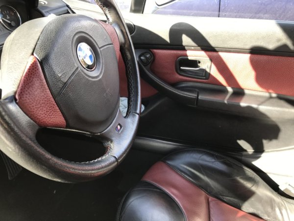
Got hold of an onboard computer, temperature sensor and OBC indicator stalk. So now to fit it

First up was to fit the temperature sensor.
Removed the offside front headlight, and behind it was a capped off yellow connector block:
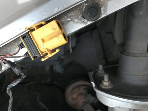
Then removed the trim panel next to the foglight. This was simple case off pushing in a retaining plastic clip and it popped straight off:

I could now easily see where the temperature probe clipped in.
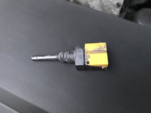
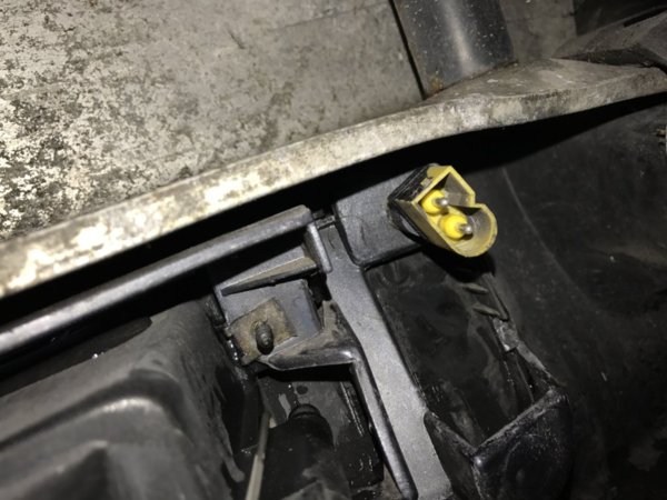
Picture from behind the bumper.
The probe needed quite a bit of force to push click in. Once in just connect up the cable.
The the trim panel went back on:
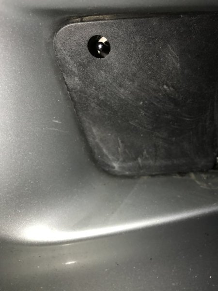
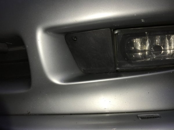
That was nice and easy.

Next was the OBC indicator stalk.
I needed to loosen the side trim of the centre console (2 screws) and remove 3 bits of trim:
- Underside of the steering wheel column cover (the part with the ignition barrel)
- The large trim panel covering the main steering column
- The small trim panel over the pedals
To remove the the lower ignition barrel trim, there is just 1 plastic screw and then the trim can be pulled down and away.
The large trim panel has 4 screws that need to be removed - numbers 3,4,5 and 6. All of these are Philips heads. You will need a stubby screwdriver to remove number 6 as it's next to the door.

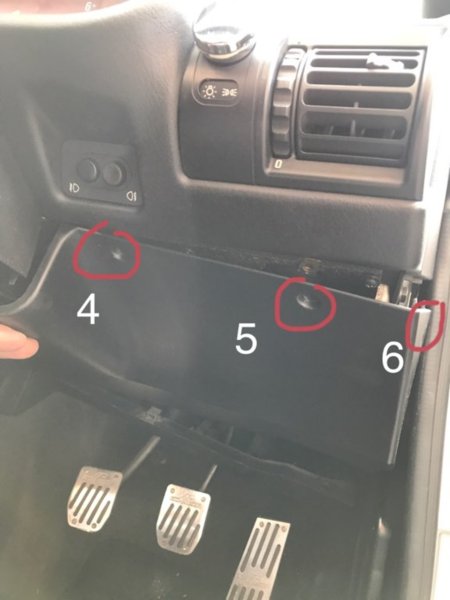
Remove screws 1 and 2 to loosen the console side panel trim. As this will aid the removal of the trim panels and allow you access to the rear of the clock which is needed later.
To remove the trim over the pedals there are 2 plastic screws. These are flat headed screws which only need a quarter turn to remove.
Once all the screws have been taken out the trim panels can be pulled away.

Now to remove the original indicator stalk and replace it with the OBC one

I have to remove the indicator stalk along with its wiring loom and connector.
This is what it looks like removed:
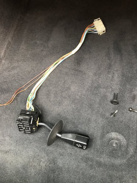
The unit consists of the stalk and a small white connector (with 2 wires) at one end and then about a 30cm of wire loom and a white connector block at the other end.
To remove the small 2 wire connection it just pulls apart. The indicator stalk is held in by 2 plastic clips attached to the stalk. One on the top and one at the bottom. Push these in and the stalk then just pulls out.

The wiring loom is held in by 4 cable tie clips. Cut these off and the wiring loom comes free. The large white connector then just needs to be unclipped to remove the unit.

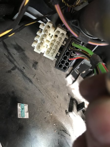
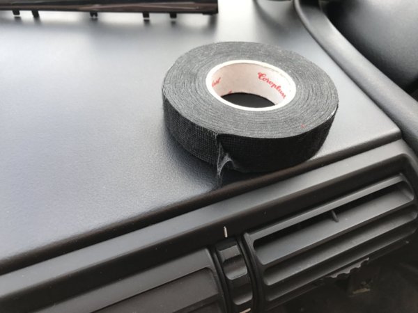
Once the unit was out my OCD came into play and I had to fabric tape the loom for my own sanity


Top one is the original. Bottom one is the OBC one that I attacked with the fabric tape.
Then it was just a case of refitting the new unit and zip tying it back in.


The last stage was to fit the new unit.
As the side trim was loosened I was able to get my hand in the side and push the unit out from behind.
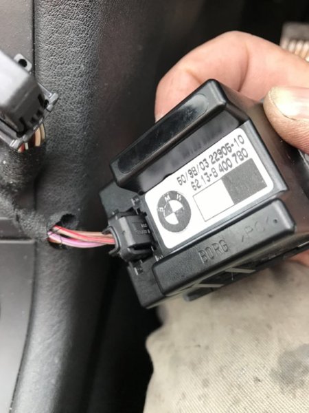
This is the back of the standard clock. The connector just pulls out. On the left of the photo is the (very poor shot) OBC connector. This is a smaller version of the types of connectors at the back of the main instrument cluster. The type that have a leaver.
Once I connected it up and pushed it in, job done

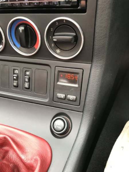
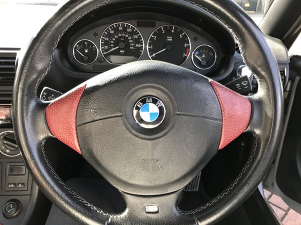
All set up and working.
As the unit came out of a 1.9 4 cylinder I didn't need to reset it or re-code it.
If it was going into a car with a 6 cylinder engine the unit would need to have been re-coded.
Hope this thread is of some use to anyone wishing to do a similar retrofit.


