Z3(00S) - EV project

t-tony

Zorg Expert (II)
Supporter
British Zeds
#ZedShed
Joined
Dec 31, 2013
Points
226
Location
Torksey Lock,Lincoln, England
Model of Z
E89 Z4 23i Auto
It never ceases to amaze me how coins find their way into seat runners etc.

Tony.
 

Tom Cheesewright

Zorg Guru (I)
Supporter
British Zeds
Joined
May 6, 2020
Points
90
Location
Manchester, UK
Model of Z
Z3
It has been a few, frustrating weeks since my last update. But there is now progress!

The inverter control board has been a source of huge pain. Not, I must point out, because of its maker. But because of a very weird fault that due to its newness, no-one recognised.

Thankfully a fellow member of the OpenInverter forum on the other side of the Pennines offered to pop my board into his inverter and check for me that it wasn't human error. Having proved it wasn't, he then went on to do some fault finding of his own, and solved it! Turns out it was a partial short on the tricky connector that had stumped me the first time around. So after a proper rollercoaster of thinking I'd solved it, then finding I haven't maybe five or six times over the last few weeks, I should later today have a working inverter.

My (sensible) plan had been to get the electric drivetrain working before I started dismantling the Z3. But I got frustrated a few days ago when there was no fix in sight and started anyway. Intake and radiator is now off, and when the rain clears I'm going to get the car up on props and drain the oil and continue preparing to remove the lump and transmission. It's going to be much easier fitting the electric drivetrain with the front of the car removed so I'm probably going to do that.

Obviously I'm going to have to replace the hydraulic power steering rack with an electric one so one of those is on the way from a fellow forum member.

I've been working on how to mount the 1-Series (electronic) throttle pedal in place of the existing mechanical one. To that end I've designed a 3D-printed adaptor for the base of the 1-Series pedal that allows it to slot on to the existing mounting and lock in place (picture shows an early version - three iterations done since then). Still a bit of work to do on a secondary bracket that will tie in to the threaded hole left by removing the pedal stop. As you can see though, it looks pretty OEM.

Next steps (not necessarily in this order):
- Get the engine out.
- Remove the flywheel and finish my adaptor design to mate it to the electric motor.
- Get the electric motor spinning.
- Finish the pedal mount.
- Make up my high voltage junction box
- Order some big batteries (£££) and the cables to connect them.
- Fit the new steering rack
- Get some steel and start to fabricate mounts for everything

Right, rain has stopped. Time to crack on!
 

Attachments

Tom Cheesewright

Zorg Guru (I)
Supporter
British Zeds
Joined
May 6, 2020
Points
90
Location
Manchester, UK
Model of Z
Z3
After a couple more highs and lows on the rollercoaster that is this project (any project?), I now have a working inverter and a spinning motor. It even has throttle control, albeit there is a lot of tuning to do - not all of which I can do out of the car or without my full voltage battery pack.

Engine remains 'almost' out. Having a real pain getting the propshaft off with limited clearance from the jack stands to get enough leverage on the torqued up bolts. Will have another go when the rain stops. After that it's just the gear shifter linkage and the mounts.

In the meantime I'm working on my ECU replacement. While the control board in the inverter does a lot of the heavy lifting, I still need something to manage cooling, provide signals to the dash, and various other bits. I've been through about ten different plans on this already. Current iteration is an ATMEGA 2560 board (loads of inputs and outputs) and a 16-way relay board housed in a 3D-printed case in the spare slot next to the existing DME (which I plan to remove). I'm hoping to re-use a lot of the existing loom for 12-volt signals, and run some shielded cable for 5V comms.

Progress elsewhere: the pedal base mount is done and printed and works a treat. Just bolts down now. The high voltage junction box has arrived and I'm ready to start mapping that out. Can't finalise layout until I know where it will be mounted and how it will be oriented in the car.

It's coming together - slowly.
 

Attachments

Tom Cheesewright

Zorg Guru (I)
Supporter
British Zeds
Joined
May 6, 2020
Points
90
Location
Manchester, UK
Model of Z
Z3
Lots of progress in the last week and a half. The engine is fully out, I've tried two different steering racks, I've changed my plans for the coupler, some of the wiring is in, and the steel for all the adaptors and mounts is ordered.

Let me break that down a bit.

Engine Removal
First, the engine. With only one minor mistake (I missed a pin on the gearbox so ripped the shifter out with the transmission - fortunately nothing damaged) and two minor breakages (the plastic heater pipes both got cracked), the engine and transmission came out. Was a fantastic day working with my daughter on everything, who proved she has excellent instincts for all things mechanical. Over the next few days we stripped out the remaining parts like the steering rack (more below) and gave the whole engine bay a really good clean. This uncovered a few spots of rust but nothing serious. Though the X-frame under the engine is not in good shape. Suspect I will have some welding to do there.

Plan is to give it another clean and a coat of paint before reassembling everything. Not original colour and not expecting a perfect finish. Just something to protect it and keep it looking fairly clean.

Anyone want an engine? Only 174,000 miles on it. But can share a video of it running nicely. Includes all ancillaries, ECU and EWS.

Steering Rack
The idea of putting a hydraulic steering rack in an electric car, when there are electric steering racks, just seems odd to me. But it may be what I end up doing. I tried a 1-series steering rack first but it was just too big in every dimension. So I thought I'd try a Mini steering rack, which looked a lot closer to what I needed. This will actually fit really nicely and I'm holding on to this option. But, the motor did protrude up into the middle of the engine bay where I will want to be putting batteries. Plus, the fewer parts I change the easier it is going to be to get this car through an MOT.

So I went back to the drawing board, or rather eBay, and bought an electric power steering pump from a Vauxhall Zafira. This seems to be the one everyone in the DIY EV community uses. We'll clean up the old rack and cooling loop and see if we can get it all hooked up.

Anyone want a 1-series steering rack?

Coupler
I'm at the stage of needing to connect my electric motor to my gearbox. I have had a plan for this from the start: design something in 3D, send it off to a company called Protolabs, and with their incredible CNC machinery they'll just knock it up for about £300 (based on a rough quote I got in the early days of the project). So, once I had the engine and gearbox out, and had separated the two, and extracted the flywheel, I finished up the design I had started around the motor splines. One thing gave me cause for concern though: the weight of that dual mass flywheel. That was going to put a lot of load on the motor bearings. Hmmm.

I cracked on and 3D printed a couple of test versions of my coupler before sending it off to Protolabs for a quote. They came back the next day with a quote of £350. I could live with that. Until I examined the quote more carefully and realised that it showed me their machines couldn't cut the splines for my motor more than about ten millimetres into the shaft. OK, so maybe it just needs manufacturing a different way. They did tell me they could 3D print metal. Sure enough, they could. For £1400.

Back to the drawing board again. While I was pondering, a chat with a fellow DIY EVer got me thinking about the quick and dirty option: find something that has the same spline pattern and weld that to one end of a tube, and the clutch centre to another. This would a) be very cheap and b) weigh a lot less, albeit with the loss of a clutch. But I won't be changing gear very often anyway...

Question was, what has the same spline pattern as a Mitsubishi Outlander electric motor. I stuck "19mm 17 spline" into Google and what comes up? A Fiesta clutch. Driving past my local garage a couple of days later (the one that has agreed to MOT my EV), I asked if I could have a dig around in their recycling bin for old clutches. Top of the pile was one marked 'FoMoCo' and sure enough, it had a 19mm bore and 17 splines. I got home and dropped it on the motor: perfect fit.

So, amongst the steel I have ordered (below) is a couple of pieces of thick walled tube. I've got a plan for how I might be able to do this at home. Obviously the ideal would be to get someone to make it up and balance it. But I have a few ideas. We shall see...

Fabricating
After a good chat with a steel stockholders nearby, I'm off to pick up a load of pieces tomorrow in return for a very large round of bacon sarnies. I'm getting a selection of box, tube, and plate that should be sufficient to make up the adaptor plate, mounts (possibly welded direct to the adaptor plate, and a frame for mounting the inverter and high voltage junction box. With a bit of luck we'll start putting that together on Friday and get a good chunk done over the weekend.

Wiring
With my daughter's help, I traced the routes from the ECU into the cabin and ran two shielded 7-way industrial cables. These now run across the ECU enclosure and out where the coil pack connections use to exit. This brings them out very close to where the 35-way connection on the inverter should sit.

One cable will carry the 5V signals from the throttle to the inverter. This is now terminated in the appropriate plug for the 1-series throttle pedal. The other routes around the driver's footwell and into the centre console where it will be connected to a forward and reverse switch that I've mounted in one of the blanking plates. It would all be soldered in but it turns out the switch I bought doesn't like heat very much. A replacement is on the way.

Lots more to tell but that will have to do for now.
 

Attachments

Mint

Zorg Expert (I)
Supporter
British Zeds
East Anglian Crew
Joined
Sep 23, 2012
Points
222
Location
Stafford
Model of Z
2.2 & 3.0 Sport
Great project and write up Tom, following with interest:thumbsup:
 

t-tony

Zorg Expert (II)
Supporter
British Zeds
#ZedShed
Joined
Dec 31, 2013
Points
226
Location
Torksey Lock,Lincoln, England
Model of Z
E89 Z4 23i Auto
Fascinating read Tom and I'm looking forward to the next installment. Wish we were closer so I could come and have a look see.

Tony.
 

Tom Cheesewright

Zorg Guru (I)
Supporter
British Zeds
Joined
May 6, 2020
Points
90
Location
Manchester, UK
Model of Z
Z3
Another week or so of big progress. Tomorrow (sore muscles permitting) I will test fit the motor and gearbox for the first time.

Adaptor Plate
The steel stockholders were great. They provided two 8mm thick steel plates, cut to size (400mm sq), 2m of 40mm box section, 2m of 20mm box section, a metre of 37mm i/d thick walled tube and a metre of 28mm i/d tube. Amazingly, I managed to squeeze all this into my Alfa GTV!

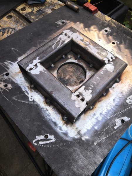
The plates are thicker than I was intending - it was a case of what they had. And I've had to crank my welder to the max to get a decent joint. But actually the measurements with the two plates and the box section in between turned out to be absolutely perfect to give the space I needed for the motor spindle.

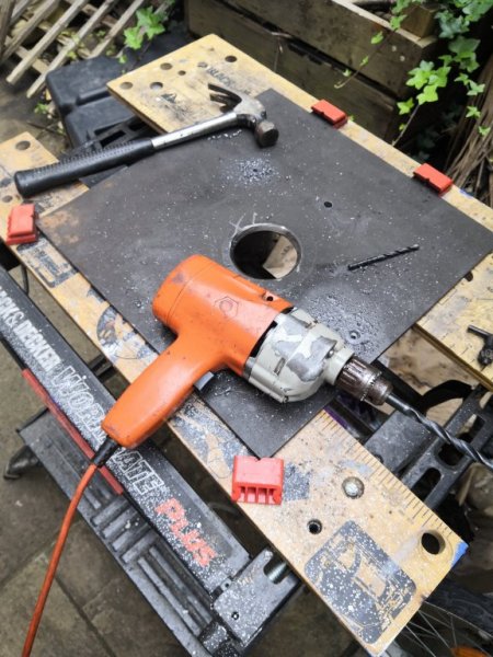
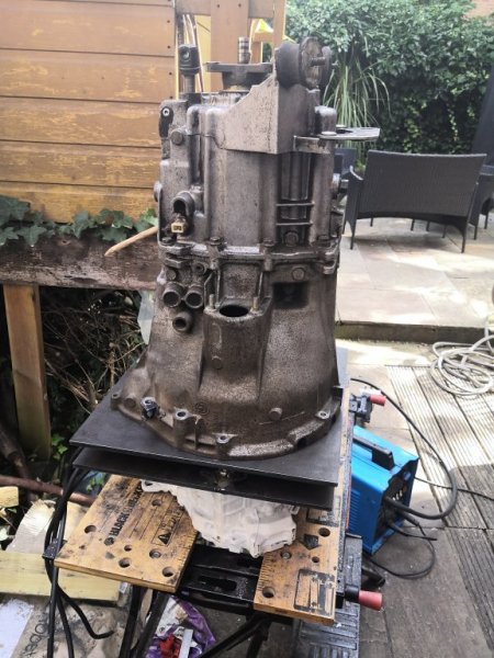
Over the last week my daughter and I have measured and drilled the holes in each plate (marking them out with a transfer punch), bolted them up to the motor and gearbox respectively, welded on some captive nuts, then welded the two plates together with a square made from the box section in the middle. It took two hole saws and a lot of sharpening of bits but we got there in the end. As of today the whole assembly can be bolted together and it is ready to go into the car for test fitting.

There's still lots of work to do on the adaptor plate. It will need cutting down to save a bit of weight. Some of the holes need adjusting. A few more welds wouldn't go amiss. And then it needs painting. But first we need to make sure it all fits, and work out how the engine mounts will bolt up. Plan is to use some of the 40mm box cantilevered off the motor plate to bolt up to the existing engine mounts. The two circles of steel cut out from the centre of the plates are actually a perfect fit for the mounts. So those will be welded on underneath. It will all make sense when you see it.

Coupler
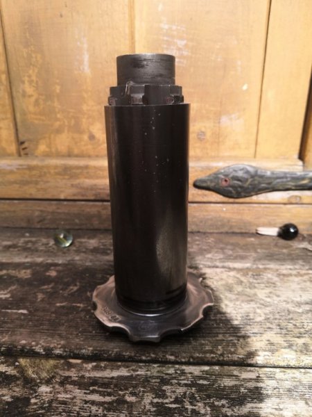
The steel tube was for the coupler to link the gearbox and the motor. Turns out I only needed the 37mm as both clutch centres will sit inside it if turned the right way around. The BMW clutch is a really nice tight fit so getting that square was fairly easy. The Fiesta clutch less so. It has funny little stepped splines that take a little balancing to get them square. And when I say 'balancing', I mean welding it, spinning it, cutting one of the welds off, hitting it with a big hammer, welding it again, until it looked pretty straight.

This just left me with the outside of the clutch centre to sort out. There's a few rough bits from where I cut it out with the angle grinder. I'd been looking for a local company to turn it down in a lathe. But then I got chatting to my neighbour from three doors down and it turns out he has three lathes in his basement workshop! It's with him now.

Before I dropped it round to him, we used it to make sure everything aligned properly before putting in the final welds on the adaptor plate. Sticking the box into gear I could rotate the prop end and watch the motor turn through the hole left by the clutch cylinder. Despite the rough way in which the coupler was put together it all seems to spin pretty smoothly. Hoorah.

CANbus
While I've been working on the hardware in the day time (when I can get away from work), I've been working on the software in the evenings. The inverter and charger both kick out data, and can take commands via CANbus. Likewise, the shunt I have in the high voltage junction box to get some more accurate current/voltage readings provides data via CAN. And I think I'm doing to need a CANbus interface for the ABS/ASC.

So far, I have hacked together a little sketch for an Arduino Mega clone - one with loads of easily accessible i/o pins - that can read the CANbus data from the inverter and change its state or trigger actions based on what it sees. The first thing it does is switch between a series of states: Off/On/Charging/Run etc. Each of these states will require a different set of actions. e.g in run, I have two thermostatic switches coded that will turn on the cooling pumps for the motor and the inverter when they reach a defined temperature. These will be triggered by relays connected to the Arduino.

Next step is to start reading in the shunt data and then mount it all in the car so I can begin interacting with the ABS/ASC. Fortunately, all the devices seem to run at the same bus speed (500kbps).

I also need to knock up a mount for the Arduino, CANbus interface, and various sundries. I bought an old ECU/DME off this forum and I plan to harvest the connector so that I can re-use the existing loom and connectors. The stuff I want to fit in won't go in the old case so I'll 3D print something that will slot into the old cradle.

Right, that's enough for tonight.
IMG_20200805_193914.jpg IMG_20200806_114020.jpg IMG_20200806_161950.jpg IMG_20200806_162005.jpg IMG_20200807_154035.jpg
 

Tom Cheesewright

Zorg Guru (I)
Supporter
British Zeds
Joined
May 6, 2020
Points
90
Location
Manchester, UK
Model of Z
Z3
Right, refreshed after a week off and time for a bit of an update.

Test-fit
After the last update I did indeed get the motor and gearbox into the car where they remain now. It wasn't as hard as I expected and it all slotted in beautifully as you can see from the pics below. A bit of 2x4 was used to level it up over the x-frame, ready for engine mounts to tack it in place.

This obviously isn't the final fitting. Some holes need opening up to fit larger bolts, the welds need reinforcing (I may need a different welder - mine struggled with the 8mm steel), and it all needs trimming and painting. But this is good enough for us to begin the big game of Tetris that comes next: fitting all the components into the engine bay and making up brackets to hold them.

Fuel-line removal
Before we got a welder anywhere near the front end, we needed to clear out the fuel lines. I jacked the car up onto stands again and my daughter and I got very mucky draining (not very well it turns out) the fuel lines and removing them along with the filter and any other gubbins (what even is that black cylinder next to the fuel tank?) This creates some nice space for running the future high voltage lines from the packs I hope to install in place of the fuel tank.

We haven't removed the tank itself yet, just clamped the lines. But we did soak all the key nuts and bolts on the rear frame in penetrating oil in preparation. When it comes off, the whole lot is going to need a good clean up and a coat of paint at minimum. Diff mounts looked OK though on initial inspection, which I wasn't expecting.

Engine mounts
We need to finish the mounting of the motor with a couple of struts to tie in to the old mounts on the cross member. Originally, I had planned to just do single struts at a diagonal from the front of the adaptor plate. But once the motor was in it became clear these might be quite awkward and uneven. Instead, having test fitted the inverter my daughter and I settled on a U-shaped bracket coming around the engine from the front plate that would allow us to do a couple of simple struts down to the engine mounts from its corners. Picture might make more sense.

This has the advantage of forming the base for the mounting brackets for the inverter and the high voltage junction box and maybe some of the cooling pumps. We set the height of the U to be right for the base of the inverter, allowing relatively easy access to the various connections - 35-way connector for i/o, AC input for charging, AC output for the motor, and DC input from the batteries, plus cooling in and out.

My daughter measured up and we cut three lengths out of 40mm box, as well as two plates from a length of 3mm strip that may once have been the mounting bracket for an IKEA float shelf. I don't have a metal blade for my mitre saw yet so this was done slightly unevenly with the angle grinder. I think that might be a smart purchase. We tacked this all together but putting it up against the adaptor plate realised it was all a bit skewed. So instead we tacked the sides of the U to the adaptor plate as straight as we could and then welded the base piece across them. That worked a lot better.

Eventually the U will be bolted rather than welded on, but a few tacks will hold it for now while we measure everything else up.

The two circles I drilled out of the 8mm plate will form the base of the final two struts. Just need to mock up the struts themselves now to get the angles right. More cardboard engineering.

Coupler
Our neighbour, Doug, dropped the coupler back round having machined down the rough nubs left from my cutting the centre out from the BMW clutch. Looks nice now. I'll probably leave it with just a couple of welds for initial testing and then if it spins smoothly, put a seam on all the way around. If it isn't straight enough he has offered to help me align the two clutch centres as he has the kit to do it on his lathe.

Heater
I chanced across a 2kw, 220v engine heater on Wish (later found it even cheaper on eBay) that might be a good alternative to my plan of sticking an electric heater core into the BMW unit. Certainly a lot less work! Does mean more water sloshing around but it will do for now and it might also be a way of warming up the batteries on a cold day. Plumbing will be interesting. Will have to step down the 350+ volts from the battery to drive it though. At least if I am to run it within specifications. Expect the heater element would be fine with a bit more juice but doubt the integrated pump would be happy.

HV Junction Box
I've been working on finalising the HV junction box. This is where the contactors sit that switch the DC supply from the battery to the inverter (and vice versa for charging). I have probably laid this thing out about 20 times before I finally took the plunge and started drilling holes in the mounting plate. Still it was only after I had drilled three holes that I realised the polarity matters on the contactors (they're not just big switches) and so my planned arrangement wouldn't work. So, two holes in the wrong places. It's only cosmetic and I'm the only one who will see it but still annoying.

The other tricky bit about making up the junction box is connecting everything together. I figured I would have to make my own bus bars and so bought a load of 20mm x 2mm copper strip. Anyone with basic maths will realise this has slightly higher cross sectional area than the 35mm2 cables I'm using to hook everything up.

The only problem with this approach is that the contactors I bought are horizontally mounted while everything else is vertical, so my bus bars have to go through 90 degrees. I started by measuring out neat diagonals, scoring lines and trying to fold the bars along a couple of 45 degree lines to make a 90 degree bend, with a couple of other vertical/horizontal bends bringing it all back into a straight line. This worked OK but the finished result didn't look great and it took a long time.

So, on my third attempt I just stuck the bar in the vice and tried twisting it with a big pair of pliers. The result: a beautiful smooth curve with hardly any work. You live and learn.

Only seven more to make...

Engine: sold
The engine went off to Scotland this week to replace one with a terminal oil leak. Didn't get that much for it (£110) but after it being listed for nearly a month I just wanted it off the drive. The buyer left me with some of the ancillaries to sell so that will get a few more ££s in towards the project. Still have the exhaust to go as well. If nothing else the cat should be worth a bit.

Even at that low price, the car now only owes me less than £500 plus transport, so I can't really complain.

Next steps
While on holiday I updated my todo list for the project which spanned two pages before I got scared and stopped. But mostly focused on the big game of Tetris now: getting all the other components laid out in the engine bay and brackets/mounts made up for them all. I'd like to have that done this week so that I can pull it all out again for finishing and painting. While it's out we'll clean and paint the engine bay and probably give the front suspension a spruce up. Think one of the front springs is knacked so that will need replacing at the same time.

The big unknown remains batteries. I have an order in as part of a big group buy via the OpenInverter forums but it is not clear when or even if that will deliver. And I'm running out of time to get this car at least functional before my self-imposed deadline of the end of the month. So might just have to take the plunge next week and buy a small pack to get me going...
 

Attachments

t-tony

Zorg Expert (II)
Supporter
British Zeds
#ZedShed
Joined
Dec 31, 2013
Points
226
Location
Torksey Lock,Lincoln, England
Model of Z
E89 Z4 23i Auto
WOW, Tom the motor does look tiny.

Tony.
 

t-tony

Zorg Expert (II)
Supporter
British Zeds
#ZedShed
Joined
Dec 31, 2013
Points
226
Location
Torksey Lock,Lincoln, England
Model of Z
E89 Z4 23i Auto
So, on my third attempt I just stuck the bar in the vice and tried twisting it with a big pair of pliers. The result: a beautiful smooth curve with hardly any work. You live and learn.
Yes, you do.

023 (5).jpg


One small thing I could've helped with ;)

Tony.
 

Tom Cheesewright

Zorg Guru (I)
Supporter
British Zeds
Joined
May 6, 2020
Points
90
Location
Manchester, UK
Model of Z
Z3
Yes, you do.

View attachment 153689

One small thing I could've helped with ;)

Tony.
Ha!

You're right about the motor and I am a *little* concerned about it. I have a feeling I may be looking for an upgrade before long. But I'm building with that in mind. For example, the other PHEV motors share the same spline pattern and may just need new holes drilling in the adaptor plate to fit for a quick, cheap upgrade.
 

Tom Cheesewright

Zorg Guru (I)
Supporter
British Zeds
Joined
May 6, 2020
Points
90
Location
Manchester, UK
Model of Z
Z3
Two updates tonight because I never got around to posting the first one about five days ago...

###

The project progresses apace...or at least it was progressing. Now hitting the limits of what I can do without some batteries. But here is where we're at:

Engine Bay Tetris
With the engine mounted, we could start working out where everything else goes. Through a process of trial and error, and lots of tack welding, we got the inverter and the high voltage junction box mounted in the engine bay, using a combination of 40x40, 40x20, and 20x20 steel profiles. The 40x40 might seem a bit excessive, especially since it is the thick walled stuff we made the adaptor plate from. But this will be the mounting point for the motor mounts that drop down to the rubber bobbins below. These are all now cut and waiting to be welded...

Welding Woes
Our skip-dived welder hasn't been performing brilliantly for the last week and needed a little TLC. A new earth clamp, some more gas (this time from Hobbyweld), along with the relevant adaptors and some new shrouds have all either been ordered and collected, or are due to arrive in the next day or so. This should allow us to do some much better quality welds when we take the motor back out and finalise it all before painting.

Cooling systems
In what has been an expensive week for little bits, I bought a load of elbows for the 10mm and 19mm pipe that will make up the two cooling loops for the inverter and the motor. I also ordered a very cheap but slightly battered motorbike radiator with 19mm fittings to go into the inverter loop. This has a filling cap so should work fine as a small reservoir. For the oil loop I will use the old power steering reservoir.

Plan is to mount each radiator and pump roughly in front of the things they are cooling. Some little plates and strips welded onto the rest of the mounting cage should hold them nicely.

Wiring
When I sold the combustion engine, I hung on to the loom, thinking I could re-use lots of it. The plan was to keep the original plugs on it and salvage the sockets from an old ECU. In reality this is looking like less of a good idea. It just leaves me with awkward shaped connectors and a load of wire that doesn't quite go where I want. So I'll keep some of the old loom and butcher some of it for the relevant wiring and hook it all up with new connectors.

I still haven't totally established what the intelligence at the heart of this loom is going to look like. Right now I'm playing with a Teensy 3.2 (for the battery management system), an ESP8266 (for an interface back to my home automation system and perhaps some WiFi-based diagnostics), and a Mega2560 Pro (for managing things like cooling pumps and ancillaries - all of which could be done in analogue fashion and may yet be).

Batteries
From the start of this project I have had my heart set on the BMW hybrid batteries. Watching the research into these on the OpenInverter forum they looked niccely designed and ideally specified for what I wanted. I did hope the whole pack from the BMW 330e would just drop in to the engine bay for a while but my tape measure soon told me that wouldn't (quite) work. It might have done if I had gone for the Lexus motor option.

I've been tracking lots of different units for sale on eBay but they seem to have gone up since I started looking. Whereas before there were a number for sale for around £8-900, now they're all up at £1350-1800.

Then, this week Jamie, a fellow OpenInverter forum member who has helped me lots on this project, spotted a pack going for just £500 on Facebook Marketplace. I contacted the seller and thought I'd agreed to purchase it, only to be gazumped when someone else could collect before me.

So, the search continues...
 

Attachments

Tom Cheesewright

Zorg Guru (I)
Supporter
British Zeds
Joined
May 6, 2020
Points
90
Location
Manchester, UK
Model of Z
Z3
It feels like an incredible amount has happened since the last update just five days ago. I have batteries. The car is stripped again. And most of the welding and fabrication is complete.

Battery wrangles
So, I couldn't quite let the well-priced battery pack on Facebook go. So the morning my gazumper was due to collect, I messaged the seller and offered him 50% more. He relented and after a little back and forth, we agreed (again) I would collect on Friday after putting down a deposit. After all the mucking around I wasn't confident I would see my deposit again or the batteries. But figured it was worth a punt.

In the end the seller was a lovely guy. Just sick of being mucked around by buyers. I had an easy journey over to Bradford and back, given how bad the M62 can be. And returned with a battery pack in the boot.

The following day we craned it out of the car but didn't get any further as we were focused on the car (below). The day after, we got to work stripping it down.

These packs are something else. Beautifully designed. Five shoe-box-sized modules are mounted in the pack along with a high voltage switch box and refridgerant cooling system. Strip the five modules out and the rest of it is incredibly light.

I got the packs out along with high voltage cables and the battery management loom. I have subsequently stripped and separated this to leave only the CANBus and power wiring for the individual modules.

This loom will plug in to a CAN transceiver and from there into a Teensy 3.2 running the SimpBMS software. Teensy is up and running and I'm just waiting on the right CAN transceiver module, which is due to arrive in a couple of days.

Battery box
Now that we have batteries we can think about how to mount them. A little shuffling around and I realised that three side by side running with the long edge parallel to the car would fit perfectly. I can stack the other two on top - leaving room for a third if I want to up the pack voltage at a later date.

The measurements for this is about 56cm by 40cm. It just so happens I have been hanging on to the frame of our old washing machine in case the steel came in useful. Its dimensions? 60cm by 43cm. Guess I'll be using that as the basis for my battery box!

More fabrication
The other thing we did on the day the batteries were craned out of the back of the car (my wife's: they wouldn't fit in my Alfa GTV), was finish our game of engine bay Tetris. We worked out the location for the oil cooler and pump for the electric motor, the radiator and pump for the inverter, and the power steering pump. When I say 'we', what I mean is my daughter came up with good idea after good idea, proving once again that her spatial intelligence is greater than my own.

Having scribbled various instructions to ourselves in Sharpie on the existing metal, we set about removing the motor and gearbox again, along with the whole steel cage that now includes the engine mounts (I had tack welded those on at some point after the last update), as well as the mounting points for the inverter and junction box. This almost worked: it turns out the the engine mounts make the cage fractionally too wide to be lifted straight up out of the engine bay on the crane, and I didn't notice soon enough. Therefore a few of my crappy tack welds from when the welder was misbehaving were ripped apart, leaving me a little steel jigsaw puzzle to reassemble off the car.

Starting very early this morning, I first (quietly) cleaned the engine bay down again ready for reassembly. We've decided not to paint it for now but instead wait until the whole car gets a respray, once it has its new body. Then as soon as it was decent to start making noise on a Bank Holiday, I started welding and grinding. I turned all the spot welds into seams at the joints and capped most of the open ends of the steel box and filled in the sections I had cut out to add captive nuts. I added (my daughter being busy today) brackets for the radiator, water pump, oil pump, oil cooler, and vacuum pump (another new arrival). I straightened up some of the brackets that had been tacked on before a bit skewed. I drilled out some of the holes for the transmission mount that were too small before (I didn't have a decent 12mm bit). And I started making a bracket for the power steering pump (which I didn't quite finish). Finally I gave the steel cage three coats of zinc primer and coated one side of the adaptor plate - now also a mounting point for various other brackets.

I still want to trim away some excess material from the adaptor plate as it is ridiculously heavy. And I need to beef up the welding on the coupler, which only has a couple of tacks on it at the moment. But then with a few coats of paint, the major fabrication is done and we can start to put the engine bay back together for good (or until something goes wrong or we decide to do it all differently.

Incidentally the upgrades to my welder were a partial success. I managed some half decent welds (pictured below), which seemed to be impossible before. But some were still absolute poop (not pictured below to save my shame). I think it's probably a combination of wrong settings and poor surface preparation now. But the welds are now strong at least, even if they aren't always pretty.

Junction box
Perhaps the most unexpectedly time-consuming part of this whole build has been the high voltage junction box. I finally completed the mounting of all the components this week, setting the resistor down on the mounting plate with thermal compound, trimming all the mounting screws to the right length, and routing the wiring through some 3D-printed retainers. I also drilled the case and fitted the glands for the 35mm2 cables, and mounted a 16-way locking connector for all the control signals. Oh, and I also made up the cable to connect up the ISA shunt, an additional monitoring device that will give me detailed information about battery performance. Last job is to solder up the 16-way connector. Fortunately, I hadn't yet done this when Jamie corrected my understanding of the way the inverter control board drives the contactors and relays in the junction box. Turns out I can do away with the relays I was using to switch these connections and run them straight off the board, simplifying things greatly.

And that will do for today's update. Especially since I've just realised that in spite of all of the above, I have hardly taken any photos!
 

Attachments

Tom Cheesewright

Zorg Guru (I)
Supporter
British Zeds
Joined
May 6, 2020
Points
90
Location
Manchester, UK
Model of Z
Z3
The problem with starting an EV conversion on an MOT failure is that you also have to address all the reasons it failed in the first place. And with a 174,000 mile car, there can be a few of them. Obviously there are no issues with the engine or emissions now. But somewhat predictably, the more I have dug around in this car, the more issues I have found.

Front corners
I noticed a few weeks ago that one of the front suspension springs was broken, so knew that would need replacing before we put the car in for a test. When I took the shock absorber off I found this was also in a pretty rotten state, with the bump stop completely mashed and split. So I figured I probably ought to replace this as well. If you're going to do one corner, you really should do the other, and suddenly you're looking at quite a bit of money. If you go OEM that is...

Trawling around for replacements though I noticed some absurdly cheap sets of coilovers to fit this vehicle. And when I say absurdly cheap, I mean I put in an offer of £195 - new, including shipping - and had it accepted. Now are these coilovers going to be any good? Absolutely not. Eventually I will have to replace them with some decent ones. But, for less than the price of doing both front shocks and springs, I get shiny new components all round with - critically - adjustable ride height so that I can balance out the weight differences from the conversion.

While I was at the corner I decided I really ought to strip off and clean up the incredibly crusty front knuckles and calipers. The bolts all came off surprisingly easily with a short breaker bar, but splitting the taper at the bottom was another matter. Again, somewhat predictably, I managed to split the boot surrounding the ball joint on the lower suspension arm. I was a bit cross about this until I realised that both suspension arms were so rusty that they too were probably going to be an MOT failure at some point. Out came the credit card again for some budget parts. Incredibly, droplinks, bushes, and full suspension arms for both sides were just £75.

That only leaves the knuckle, caliper and brakes as the original components. If I had more money I would probably replace all of the above. The knuckles are very rusty, albeit mostly just on the surface. But the tinware around them is totally shot. And the flexi pipes are completely seized on the calipers. Not sure how I am going to get those off for a proper clean-up yet.

Finally, while I'm taking the front end to pieces, I noticed some fairly serious corrosion on the X-frame brace. I took this off and hit it with the wire wheel and it is pretty bad: great big holes. It's not distorted though, and between the holes there is some solid metal. I'm going to have a go at welding this back up once the rust I can't get to has been treated.

I picked up some Hammerite today so plan for this weekend is to remote the remaining suspension and brake components (if I can), give everything a thorough clean and a coat of paint ready for refitting. Will need a new wire wheel for this though: wore mine down to the metal cleaning up the brake rotors and the X-frame.

Battery Box
Meanwhile in the evenings I've been doing a lot more planning of the battery box. The washing machine case sadly won't provide all the steel sheet I need. But its top and bottom frames will give me a great starting point. Plan is to cut all the way around the frame just below the door, giving me about a 30cm tall box. I'll then drill out the spot welds from the other end of the frame and weld that frame into the top for support.

Inside this box will fit two rails. I have some thick rectangular steel bar, about 14mm x 8mm that will work well for this. I will drill and tap M6 holes into this bar to hold threaded rods that will rise up through the pairs of holes at the end of each of the battery modules. This will allow me to stack them up on top of each other with some space in between.

Cooling is an interesting question. I had thought I would just go with air cooling at first, but this opens up the possibility (perhaps likelihood) of moisture getting into the battery box: not ideal. Shall have to mock it up and keep an eye on temperatures.

Wiring Loom
Final part of this update: I've been continuing with the wiring loom. Getting rid of most of the old loom was the right plan. The new loom is actually relatively simple by comparison with all the sensors the old ICE required. Mostly just power and CANbus flowing around. I plan to daisychain the CANbus connections: car (ABS/dash), to VCU, to inverter, to charger (part of inverter but has separate CANbus interface), to high voltage junction box, to battery box. I've decided to handle any step down to 5V inside each component, so that I'm only routing 12V power. That should reduce the chance of stupid mistakes and make wiring easier.

Where it gets a bit more involved is routing switching and control for the various pumps - water, oil, vacuum, power steering. Will handle that once they're all in the car though.
 

Attachments

Tom Cheesewright

Zorg Guru (I)
Supporter
British Zeds
Joined
May 6, 2020
Points
90
Location
Manchester, UK
Model of Z
Z3
Two steps forward, two steps back...

Right now, I wouldn't begrudge the authorities denying to approve my car for the roads, and possibly taking my licence, given that my spatial awareness is so bad I seem to have believed that two different components could occupy the same space in the engine bay. Let's rewind...

Front-end rebuild
Somehow it has been over a fortnight since my last update so this one is a bit of a monster. During that time there has been lots of activity, but work has been ramping up and in my infinite optimism, I also signed up for a course in something completely different earlier this year which requires lots of reading. Suffice to say I'm not exactly flush for time right now, so while things are getting done I'm getting worse at documenting them.

Also, with my daughter now back at school and clubs, most of the work has fallen to me now. So with only occasional help, I finished stripping all the components off the front end, wire wheeled everything, repaired some rust (notably on the X-frame that ties the front end together), and gave everything good coat of Hammerite.

Then, I did it all in reverse, this time with new lower suspension arms, bushes, track rod ends, and drop links. Oh, and a new set of coilovers. This has not all gone smoothly. Firstly, I couldn't get the new bushes into their mounts. I didn't want to spend £60 on a cheap press, not because I didn't want one but because I didn't want to have to store it. And none of my local garages would take the job on - or even had a press. In the end I bought some new mounts with the bushes already fitted. I'll either keep the spare parts or sell them on.

For a measly £195 I'm very happy with the new suspension, including rear shocks and springs and coilovers for the front. I got the coilovers compressed down and fitted to the old top hats without too much issue. Except for the massive scratches I seem to have put in the dining room table. Whoops. I even managed to cut out some new gaskets from a sheet of gasket paper on my wife's CNC paper cutter (see pics)

The problem came when I got them on the car: the springs rub on the tires. Reading the forums it seems this is a fairly common problem. I'm going to be changing the wheels anyway, so I'll think about this properly down the line. But for the time being I have kept the front end jacked up and ordered a very cheap set of 10mm spacers. I'm hoping this is enough and that the original wheel bolts are long enough.

Headlamps
One quick job was restoring some very milky headlamp covers. I could get them much better with a little more time, but I good going over with metal polish and a microfibre cloth worked absolute wonders. Good enough for now, since they won't be on the final car after the body conversion.

Battery Box
One thing that was a little more interesting was the battery box. My daughter and I started executing my cunning plan to turn an old washing machine into a battery box not long after the last post. We sliced out the middle third, around the door, then began welding the top and bottom sections together to create a box with enough space for 6 BMW cells in a 3x2 configuration. We need some more steel to finish it but it is now pretty solid, and great for mocking up (below) as it is pretty light still.

The original plan had been to mount the six batteries onto two thick pieces of steel bar I had lying around, with threaded rods coming up through the holes at each end. But then I had a bit of a brain wave. The original case already has perfectly spaced threaded holes sunk into it in the right orientation. Why not just cut that bit out of the box and bolt it into the bottom of my battery box? We shall see how that goes.

I also plan to re-use the original lid, cut down to the same size as the battery box. It has holes in the top that will match up to the threaded rods.

Battery Management System
I'd written most of this blog post before I remembered I'd done this. I stuck the SimpBMS software on a Teensy 3.2 microcontroller and hooked it up to the BMW cells via a CANBus Transceiver. Incredibly, it worked first time giving my nice clear readings of the voltages across all my cells. They're all sitting pretty low at 3.6-something (it was a couple of weeks ago now) but with very little delta, which is a good sign. As soon as I get a charging system hooked up I'll give them some juice.

I have stripped down the loom from inside the battery box and remade it with just the bits I need and then re-wrapped the lot in cloth tesa tape. The BMS itself is now mounted in a custom 3D-printed case. It's not amazing (there are still a load of jumper wires in there), but it will do for now.

The battery box came with both high and low voltage connectors, including a locking ampseal plug on the outside with all the tails just cut off. I plan to re-use this and have 3D-printed a shround to cover the wire exits. I'll just splice my own cables into this rather than starting from scratch. I've also knocked out a little clamping plate so that it can be fitted to a cut out of the sheet steel in my new battery box.

For the high voltage connection I have designed something similar to the shroud I made for HV connections on the inverter. It's not totally finished yet but only needs a little polishing. What I don't yet have is an emergency disconnect. Still thinking about that.

Charger
My plan for now is to use the charging capability of the hacked Prius Gen 3 inverter. The only problem being that it doesn't come with this capability out of the box. No-one has written the software yet and I've had no joy getting the Atmega chip that runs it to take code. So, I've ordered one pre-loaded with a bootloader and will get my local soldering genius to swap the chips when I can get over there.

Heater
Another thing I almost forgot before I looked at the photos from the last fortnight: I have modified the cheap Russian AC water heater module I got to disconnect and remove the pump from it, leaving just a nicely encased 2kw heating element with 19mm barbs for inlet and outlet. See pic below (I need to take more photos!).

I've removed the final pipework and solenoid from the heater matrix, leaving just two 19mm barbs sticking out of the firewall. I just need a reservoir, another pump, and a temperature sensor now and I should be able to set up a nice little heater loop.

I'm planning to power this off the full battery voltage, so will likely need an extra contactor. Considering using one of the ones from the BMW battery pack.

Assembly
With the front end back together and looking all clean and shiny, it was time to start adding all the good stuff in. While everything was back out of the car I had welded brackets or at least captive nuts for various ancillaries on to the adaptor plate or the combined motor mounts/mounting brackets for inverter and high voltage junction box.

My daughter and I first bolted the transmission to the adaptor plate, using a mixture of the original BMW bolts and fresh ones. We might go back and add some threadlock once it is all working. We then added in the coupler, which I'd done some welding on while it was out of the car. I've added a couple of weld around the press fit between the gearbox splines and the tube, and around the Ford clutch centre that mates with the motor splines. I then filed all this back as neatly as I could. Is it balanced? Only one way to find out. I sort of wish I had done a full seam between the BMW centre and the tube but it does seem very solid. Maybe next time it comes out I'll do that and see if someone can balance it.

Next step was the motor, which slotted on and bolted up surprisingly easily. Getting the splines to line up has been a bit of a pig in the past.

With the unit altogether I looped some straps around it all and we craned it into place. After a bit of shuffling back and forth we managed to get the propshaft aligned, the front mounts in place, and the gearbox sat back on its mounts. An hour or so under the car and I had all this bolted up as well as the bolts between gearbox, giubo (check out the spelling! No, me either) and propshaft in loosely. Everything will need torquing up at some point. Maybe some more threadlock too.

First thing I noticed: the motor mounts (and so everything riding on them) have come out a little skewed. It's not major and it won't prevent the car running. But I think it's going to annoy me eventually. This was the least of our problems though...

Where to begin? The oil cooler mounts for the engine cooling circuit are a fraction - maybe a centimetre - too high. So the output from the motor and the input of the cooler don't line up. And they're too close together for a curved bit of pipe. The idea was I could just use a straight short to connect them. Since I really don't want to take the adaptor plate to which they are welded out again, this is probably going to require some brute force engineering as I bend the mounts to make it all fit.

The oil pump mounts require some shorter bolts. This is fine, but it meant I need to get some more or cut some down. Either way, it didn't get attached today.

I had made a mount for the PAS pump. I knew this one needed some finessing so I left it in two parts that could be welded together once I tested the fit. Unfortunately, leaving these two parts separate only allowed for adjustment in one dimension and I need to adjust it in two. So more fabrication to do.

Then we get to the real problem: the inverter mounts and everything that hang off it (coolant pump, radiator) will foul where the battery box should fit. How I didn't realise this I have no idea, but it became pretty obvious when I fitted it all this time. The inverter needs to move up, left, and back to clear the battery box. And the ancillaries need relocating completely. To where, I'm not yet sure.

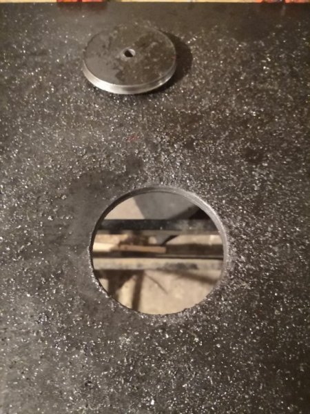
So, out came the grinder. I masked off as much off the engine bay as possible with carboard before cutting, but the dust and particles still get everywhere. I'll need to grind back some of my nice new paint to weld in some new mounts but this can all be done in situ now - especially now my welder is working better. On top of new gas and a new earth clamp, I have now rebuilt the torch, resulting in much less play in the swan neck and much better control of gas and wire flow.

Next steps
So (this has been a very "So..." blogpost. Sorry.), instead of just wiring and plumbing it all now, I obviously have a fair but more fabrication to do. I'll probably start with sorting out the PAS pump and the cooling loop for the motor, since those are all in the least accessible places. I forgot to mention above that the vacuum pump mount was actually perfect, so I just need to work out how the pressure switch I secured works and hook all that up.

Then I will move on to the battery box and get that finished up. Will be great to get the batteries actually into the car, though I might want to test charging them outside of it to start with! With the batteries in I can adjust the coilovers to get a decent ride height.

Finally, once the battery box is made up and mounted, I will remount the inverter. In the meantime I'll likely eke out some hours to get cracking with the wiring now that the position of everything is pretty much finalised. I still need to make a case for the vehicle control unit was well, something I have been going around in circles on the design for.

That all done, I still need to get around to the back of the car, changing the rear suspension, dropping out the fuel tank, and seeing if any remedial welding is needed at that end (I didn't even mention that I had patched one of the sills - needs redoing more tidily but it has stopped the rot for now).

Until next time...
 

Attachments

t-tony

Zorg Expert (II)
Supporter
British Zeds
#ZedShed
Joined
Dec 31, 2013
Points
226
Location
Torksey Lock,Lincoln, England
Model of Z
E89 Z4 23i Auto
A very interesting read Tom.

Tony.
 
Top