Z3(00S) - EV project

Tom Cheesewright

Zorg Guru (I)
Supporter
British Zeds
Joined
May 6, 2020
Points
90
Location
Manchester, UK
Model of Z
Z3
It has been three weeks since my last update. The pace of this project has definitely slowed as work has picked up and the weather has worsened. Nonetheless, there is plenty of progress to report. Unfortunately I haven't been great at taking photos this time around so forgive the paucity of pictures.

Battery Box
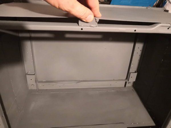
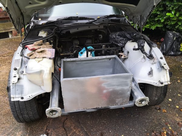
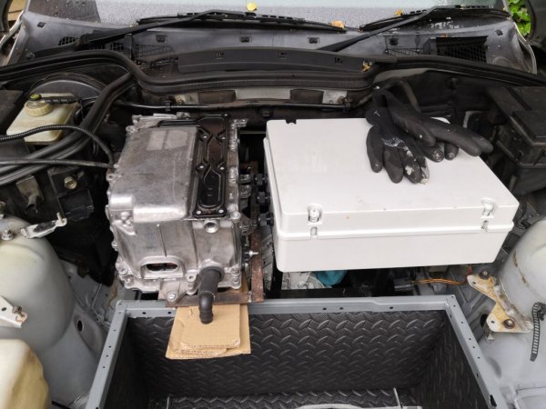
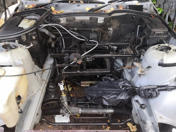
After my disastrous spatial miscalculations of the last update, I decided I wouldn't try fitting anything else until the battery box was actually done. This has taken a lot longer than expected. For a start, I needed more steel than I thought to get a properly sealed box all the way around. One of the washing machine panels I was going to use bowed out at the top and trying to rejoin it to the frame in a way that made sense was just too much work. So I cut it off and replaced it with a fresh piece of steel, as well as adding one to the bottom, and a patch to the back to make it nice and square all round. The welding isn't exactly pretty but I'm slowly getting more consistent and only occasionally forgetting to turn the gas on.

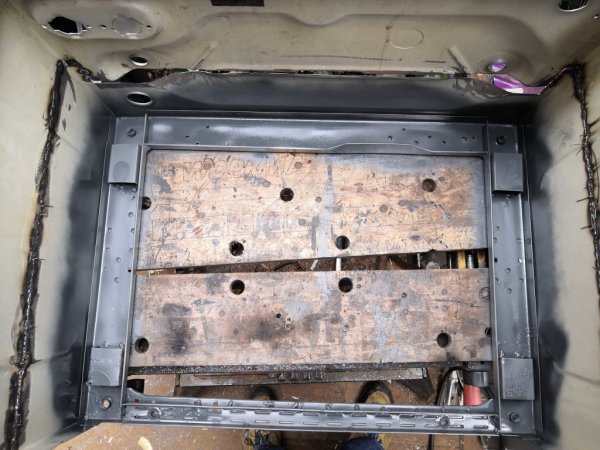
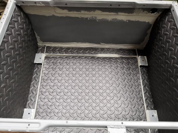
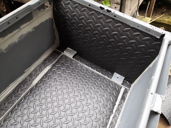
Before I put all the new panels on though, I needed to fit the base plate from the original BMW box. This being aluminium, I couldn't weld it, so instead I welded in four standoffs to the base of the box and drilled them to accept rivets. Having trimmed and neatened the base plate up with the grinder, I dropped it in, drilled through, and test-riveted it. It worked beautifully.

So, the flat panels were welded on, and the whole lot was given a coat of zinc primer. Next up: mounting it in the car.

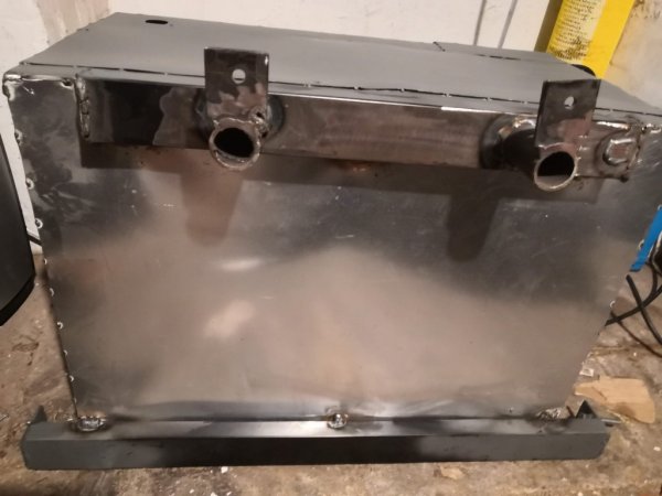
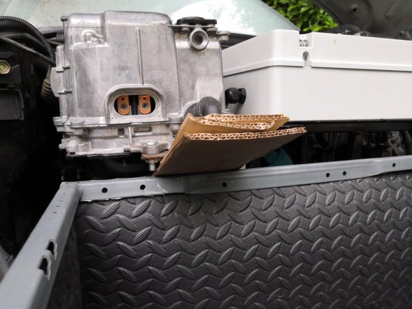
This was a little complicated. The box had to sit above the steering rack and protrude out almost to the radiator where there was nothing obvious on which to mount it. At the back, I concocted an arrangement of 40x20mm box section welded to two circular standoffs that straddle the steering rack bolts into the front cross member. Two pieces of plate then extend towards the back of the car from these standoffs with holes to line up with unused 8mm holes in the cross member. This took a lot of measuring and tacking in-situ before it could all be welded up and ultimately, welded to the bottom of the battery box.

At the front I decided to re-use the radiator mounts, since these will no longer be used. They're inn pretty good shape and tie directly to the front frame so should be strong enough, though I can always reinforce them if needed. Another piece of 40x20mm box spans the gap between them with little lips sticking up, drilled with two more 8mm holes that pass through the radiator mounts. Again, with it all in situ I tacked it to the bottom of the battery box then removed it for some proper welds.

Given the way this has been constructed, it's far from water tight, so I've bought some brush-on seam sealer to go over all the welds, joints and gaps. Once this is applied, I'll be adding a layer of EVA foam (OK, yoga mat) insulation all the way around before refitting the base plate.

This leaves two final jobs: the high voltage connector and the lid.

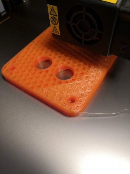
I prototyped a design for the HV connector on my 3D printer which showed up all the flaws: I'd over-sized the spaces for captive nuts and undersized the holes for the connectors. But version two is well on its way. In fact it is two thirds printed but my printer decided to throw one of its periodic tantrums half way through the third component and I haven't had time to sort it yet. I may also need some more PETG. Once I have tested the design I will share it like all the others.

For the lid, I plan to reuse the lid of the original battery box, cut down to fit. This will need a little modification on the underside to create a good seal (probably bonding on some flat strips of aluminium and using more EVA foam). But it looks great. It's all marked up and just needs cutting now. I plan to rivet an aluminium panel to the front of the box with holes that match up to those on the lid so that it can be bolted down.


Inverter Mount
About five times over the last three weeks I have dug out the inverter, balanced it in various positions in the engine bay, muttered swearily, and put it away again. On the sixth attempt, I had not exactly an epiphany but at least an idea of how it could be mounted.

I found some fairly thick (maybe 2.5mm? I should probably check) bar in the cellar and decided I could make a U-shaped cradle from that to pick up the Prius inverter's three mounting points. I mocked this up in cardboard before cutting some strips to length with the handsaw - limited time now means earlier starts on the weekend when using the grinder might see my neighbours turn violent. Fortunately the welder is relatively quiet so I tacked the pieces together before checking the fit, then welded it up properly along with some captive nuts. It's not as stiff as the 20x20 box that the HV junction box frame is made from. But once it is welded in it will be stiff enough. A diagonal of 40x20 at the back and two 20x20 uprights will tie it into the rest of the mounting frame.

Cooling
This just leaves the cooling for the inverter and motor. With the battery box in place, I can now see that there should actually be space in front of it for both radiator and oil cooler. This will mean longer pipes than I planned but it will make mounting nice and easy as I can just tie into the slam panel. Plenty of room to route the pipes around the side of the battery box.

Now I just need some time and some decent weather - ideally decent weather precisely when I have some time!
 

Attachments

Tom Cheesewright

Zorg Guru (I)
Supporter
British Zeds
Joined
May 6, 2020
Points
90
Location
Manchester, UK
Model of Z
Z3
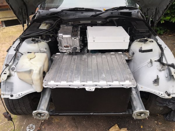
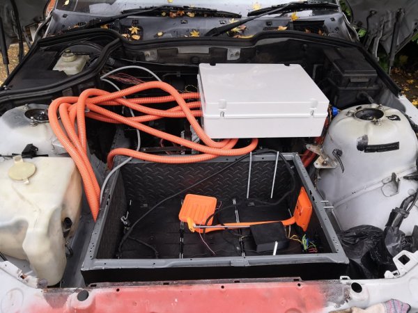
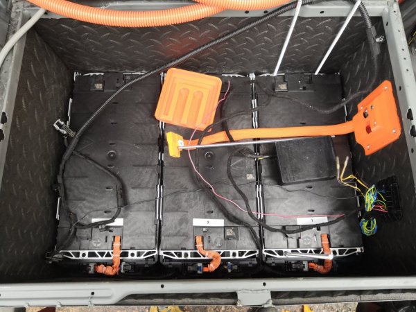
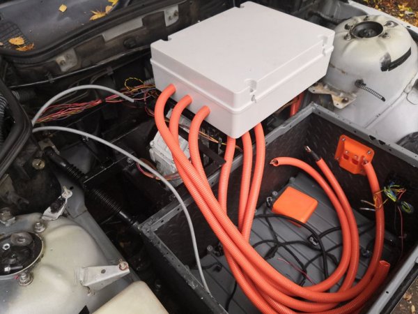
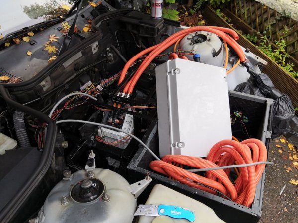
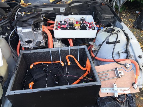
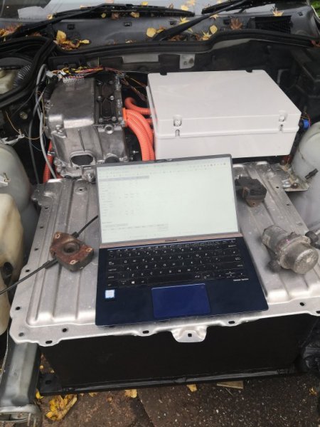
Little update after a bit of work the last couple of days: battery box, inverter and high voltage junction box all now in and ready for some wiring - both high voltage and control. Got some of the 3D printed connectors/adaptors I've knocked up in as well.

Photos show me mocking up the location of the inverter with cardboard and wooden wedges so I could measure out the new steel for the 'cage' that combines the motor mounts and frame for this and the HVJB. Measured up, pulled it all back out (again), and welded it up. Then slapped on a coat of Hammerite. Eventually I want to take this all off and remake it a bit better, or at the very least repaint it properly.

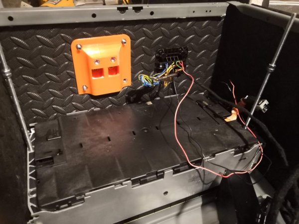
Other pics include the lining of the battery box (cut from EVA foam (yoga mat) and glued in), some connector close-ups, and it all now in situ.

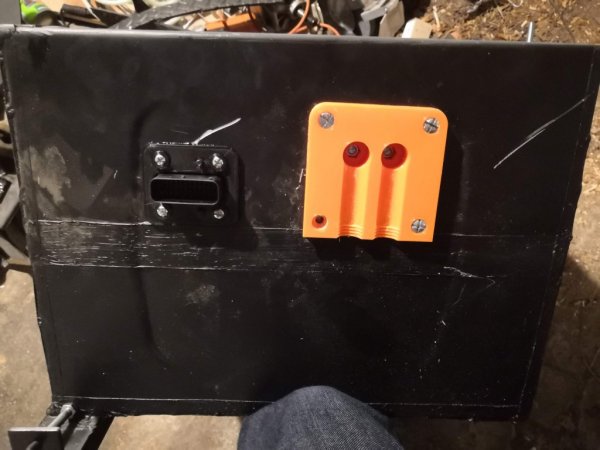
- The orange high voltage connector has a cover that slides over it and screw-in locks that also hold the sheath for the 35mm2 cables. I'll post some photos of that soon.
- The black connector is a combination of a salvaged plug and socket and a 3D printed front plate. The plug that came with it lacked any sort of cowl or sheath so I've also designed and 3D-printed one. I'll post some photos of this as I go through the wiring too.

Issues: I had to push the inverter so far back to clear the battery box that there isn't much space for the AMPSeal connection that carries all the control/communication wires or for the water cooling inlet/outlet (TBC). Think I can clear some space for the cooling with some slight bends in the brake pipes that run across there.

AMPSeal is trickier but have a plan: the riboon cable I have in there that connects the control board to the AMPSeal is far too long. So will swing the connector through 180 degrees and mount it under the inverter where there is now loads of space. OR come up with something completely different.

Next step: running CANBus, 12V and HV cables. Then I'll think about cooling again - got some ideas...
 

Attachments

Tom Cheesewright

Zorg Guru (I)
Supporter
British Zeds
Joined
May 6, 2020
Points
90
Location
Manchester, UK
Model of Z
Z3
This week I have mostly been focused on getting the car wired up.

Inverter connection housings
With the battery box and inverter mounts in, the first issue I had to solve was the connections on the inverter, which were now fouled at the back by the firewall and at the side by the wheel well/strut housing. I tackled the low voltage connections first, looking at various ways to re-route the large 36-way AMPSeal connector that comes with the EVBMW kit. Initially I was thinking the connector would have to go underneath the inverter, which would have been a total ballache. Then one day I left the loom I was making up sat on top of the inverter and realised there was just about enough space there.

I took my original design for the AMPSeal housing and flipped it through 180 degrees so that the connector came out on top and pointed towards the front of the car rather than the back. Then I added a shell to the back to leave space for the IDC cable that comes from the inverter and the connectors. Amazingly I nailed most of this first time, after some major 3D printing issues. However I didn't leave quite enough space for the solder tabs on the back, meaning I lad to print an extra shim to give enough space. I'll revise the design down to two parts at some point but have posted my current version here.

This all fits beautifully, as you can see. Very happy with this layout as it gives nice easy access to the connector.
inverter_ampseal_2.jpg
inverter_ampseal.jpg


What I haven't done yet is sort out the high voltage connections on the side. These already needed work as I now need three connections: one for ground, one for driving the motor, and one for charging/the DC-DC converter. I think I explained this in a previous post, but basically I have an extra contactor in my high voltage junction box that allows me to engage or disengage drive so that when the inverter is acting as a charger, juice can get to the batteries but not the motor.

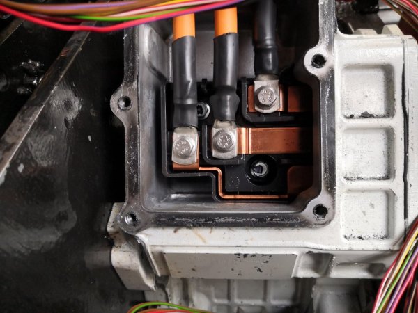
In addition to adding the third terminal, I also need to shorten the whole assembly by a centimetre or two so that it doesn't foul the side of the engine bay. Shouldn't be too hard I don't think, though worst case I may need to have the brass standoffs I got from EVBMW turned down slightly. I certainly need a third one making up.


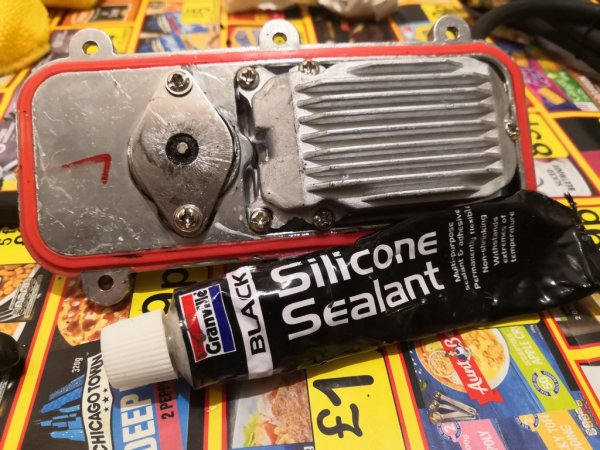
Since I wrote the above I have now redesigned the high voltage connector, knocking about 20mm off the depth, which should be enough to clear the side of the engine bay. I've also added the third terminal for charging. I've ordered some shorter brass standoffs without the flange on that the EVBMW kit has. Beautiful as those are, and useful as the flange is in holding my 3D-printed shroud in place, space is really at a premium for me. The 16mm diameter standoffs I have ordered will still give 100% contact to the crimp terminals at the end of the high voltage cables. And I plan to silicone in the shroud so it doesn't move.

Wiring Loom
I've never made a wiring loom before, but all the instructions I have seen (kudos to Jared at Wrench Every Day) say take it piece by piece, start at one end and slowly build it up. So this is what I did. I started with the battery box since this is where one end of the CANBus terminates, with the connection to the Battery Management System (BMS) I knocked up in a previous post.

One of the other things most guides to building a wiring loom tell you not to do is re-use cables. But I hate waste and all the wires in my BMW loom seemed to be in really good condition. Plus it wasn't worth much to sell, so I decided to butcher it and re-use as much as I could. I'd already salvaged the exterior plug from the battery box so I started with this and added some nice long tails to the relevant connections, noting all the wire colours and pin assignments as I went along.

I then took this first piece to the car, put the connector in place and ran the wires to the high voltage junction box, or as close to the new auxiliary fusebox location if that was where they were due to go. I then trimmed the wires to the relevant lengths and started on the junction box connector

I didn't have a any good salvage parts for this so a few weeks ago I ordered a nice waterproof 16-way connector from AliExpress. This was actually reasonably easy to wire up, and has enough pins to carry individual positive and negative feeds for each of the contactors and the pre-charge relay, as well as power and CANbus connections for the shunt. What it can't carry is connections to sense the position of the three contactors. The Gigavac contactors I'm using all have a second set of tails to allow you to sense whether they are open or closed, which it would be nice to sense and send to my VCU for debugging. Or I could just stick three LEDs in the side of the HVJB. This could just be me gold plating things though.

hvjb_plug.jpg
hvjb_connector.jpg
battery_box_connector_2.jpg


From the HVJB the loom goes to the Inverter and its 36-way AMPseal connector. From here it splits off in multiple directions:
  • to the motor for temperature and position sensing
  • to the cabin for throttle position (one 7-core cable), fwd/reverse switch, ignition sensing, brake sensing and cruise control (second 7-core cable)
  • to the VCU (CANBus, plus third temperature sensor (oil temp) from the motor)
  • to the new auxiliary fusebox (for obvious things)
loom_in_progress.jpg


Inside the space where the ECU used to sit (nicely water-sealed with lots of re-usable rubber grommets) I've hacked out most of the old wiring. Five bundles still enter this space:
  • The X6004 bundle (for BMW nerds) gives me CANBus to the instrument panel and the ABS/DSC system, as well as various other outputs to control the instruments. I've not tapped into this yet but aside from the CANbus, these will mostly be linked into my VCU.
  • Three medium-sized wires (I'm no good on gauges) come up through a four-way ampseal connector (I've salvaged both sides). One provides me with a switched live signal from the ignition and based on the BMW colour coding (red and white) it looks like it takes a return switched live, though this is currently disconnected (I'm sure I'll find out what it was meant to do when something doesn't work). I have linked the switched live signal to a 12v relay and from there to the auxiliary fusebox, an 8-way affair I picked up on eBay. Most of the things I want to drive only need to be on when the car is on, running, or charging. I will configure something to trigger this relay when the car is charging as well.
  • Two fat red wires provide permanent live, splitting into two, two-way connectors which again I have salvaged.
  • Three brown wires head off to earth
  • Two more wires come up into a two-way connector and honestly I haven't worked out what those are for yet
I have now added female spade connectors to most of the positive connections so that they can be attached to the auxiliary fusebox. And I just soldered the negatives to the chopped off earth wires, though I will need some more when I add the VCU and monitor

The two shielded 7-way cables my daughter and I chased through the firewall a few weeks ago have now been spliced into the relevant places in the cabin. An extra crimp connector salvaged from the four-way AMP connector above gave me a 'push to make' signal from the brake pedal to give the braking signal to the inverter. And I traced the ignition cable to the keyswitch and spliced a connection into this for the 'start' signal the inverter requires. This all leaves me with only one tell-tale sign that this is an EV in the cabin: a fwd and reverse switch in the centre console. When we've done the body conversion I might look for a more subtle alternative.


butchered_amp.jpg
recovered_connector.jpg
brake_pedal_connector.jpg


The throttle signal cable terminates in a four-way connector salvaged from the old loom, since two of the wires are just 5V and two are for GND, leaving the last two being actual signals from the throttle position.

The rest of the signals are currently terminating in a connecting block, but a six-way male/female AMP pair is on its way.

Once everything is tested and working, the loom will be wrapped in cloth tape and routed through grommets where possible.


VCU
I now have a rudimentary vehicle control unit knocked up. It's a little bodged together with dupont pins and jumper cables at the moment but it works. It takes information from the inverter over CANBus and right now uses the inverter state to turn on or off some of the eight way relays. These allow me to turn some things on only when the inverter is in 'run' or 'charge' mode (like cooling), and do some thermostatic control. I can also pull temperatures from the inverter over CANbus (including the motor temperatures) and I plan to measure the motor temperature directly as well (there are three thermistors in there and the inverter only has connections for two).

vcu_monitor.jpg


I wrote a little test-script for the hardware for my vehicle monitor to make it cycle through the state codes the inverter sends as a test, and the VCU does exactly what it should for now. Simple but pleasing nonetheless.

The VCU will also be responsible for parsing data from the inverter and feeding it to the instrument panel - e.g. RPM, coolant temperature etc. All that work still to come. And it needs properly boxing in too.

I'll post all the hardware details and pin connections for the VCU over on the components page when it's done, along with designs for the final case.

Monitor
I want to be able to keep an eye on the state of my car when it's on the driveway and charging, as well as maybe having some remote control for warming it up etc. To this end there will be an extra device on the CANBus: an ESP8266 running esphome. ESP8266s are my favourite little chip. Cheap and plenty capable with integrated WiFi. With the addition of the MCP2515 CANbus interface, I should be able to feed all the data I want back to Home Assistant.

The hardware on this is all done now and since it's not a critical part, I'll probably leave it as is. I've designed and printed a simple case for it that with some silicone should keep everything nice and sealed and dry. Only question is how well the WiFi will penetrate with all the noise - especially when it's charging.

Inverter as charger
Final part of this very long update. I've finally stripped the EVBMW board back out of the inverter and dropped it off with my local repair shop to have the microcontroller for the charger replaced with one that already has a bootloader on it. Not sure if I documented this but I and others have had no joy getting a bootloader onto these chips through the normal means, but it seems to work fine once you swap it out for one with a bootloader pre-loaded.

With this in place and a few more bits of hardware (a caravan-style mains connector), I should be ready for the extremely scary prospect of charging my batteries up if/when there is some software available for this function.

This isn't plug and play. For example, you need to ensure that the inverter capacitors are pre-charged from the AC or from the batteries before you dump current into them. But 240V mains plus 300V DC. What could possibly go wrong?...
 

ukcerb

Regular Member
Joined
Nov 7, 2017
Points
20
Good progress and sounds as though you are nearly ready for testing. As you say what could go wrong! Is there a way of retaining a heater in the car from the electric cooling circuit?
 

Zag2

Zorg Legend
British Zeds
Joined
Oct 30, 2020
Points
79
Location
Reading, UK
Model of Z
BMW Z3 2.8
Love this project! My long term plan is to electrify a Z3 as well. Will wait for the prices to come down first though as its all very new.
 

Tom Cheesewright

Zorg Guru (I)
Supporter
British Zeds
Joined
May 6, 2020
Points
90
Location
Manchester, UK
Model of Z
Z3
Good progress and sounds as though you are nearly ready for testing. As you say what could go wrong! Is there a way of retaining a heater in the car from the electric cooling circuit?
My plan is to keep the heating circuit separate. No point introducing heat into the inverter coolant loop which shouldn't produce much useful heat for the cabin and (I hope) will run quite cool. I have modified an off-the-shelf A/C heater unit to remove the pump so it should run at 300V DC OK. Then I just need to add an external 12V pump hooked up to the switch that normally opens the solenoid valve to route water to the cabin. That's the hope anyway!
 

Attachments

Tom Cheesewright

Zorg Guru (I)
Supporter
British Zeds
Joined
May 6, 2020
Points
90
Location
Manchester, UK
Model of Z
Z3
Two updates back to back now as I am a little behind! It has been a bit of a rollercoaster.

##

So, the wiring is now largely done, and it's time to start testing

High Voltage
35mm2 cable is pretty awkward to work with. Working my way around the car, I worked out the lengths I needed for each of the connections - battery box to junction box, junction box to inverter, inverter to motor - and cut lengths off before crimping on connectors using a borrowed hydraulic crimper (thank you fellow forum-member Alfred/@Maker_Of_Things). I then added a layer of adhesive heat shrink over the crimped parts (also thank you Alfred!)

With the cables made up, I cut matching lengths of bright orange shroud to go over them and began wiring it all in. Because this stuff is pretty stiff, getting it to stay in the right locations while you get a bolt in or a nut on can be tricky - especially in a cramped engine bay. So as you will see from the photos, I actually unbolted some stuff for connections before bolting it back in.

I'm still experimenting with my 3D-printed connectors and shrouds and I'm not very happy with them yet. The pared down connector for the side of the inverter that was tight against the engine bay wall works well enough. And I'm happy with my shroud for the motor connections. But neither of them hold the shroud as I designed them to do. Bit more work required to tweak those before I share them.

The worst connector was for the battery box. This was incredibly fiddly and I don't think it shields the two connections from each other enough. Back to the drawing board on that one.

12V Loom & testing
There are still some connecting blocks to be replaced with proper connectors, and I haven't yet wrapped it all in fabric tape, since I'm sure I will have screwed up somewhere. But there is enough stuff in the car for testing. The first bit of which we did today.

We sat in the cabin, turned the key and watched the WiFi network from the inverter come up. We logged in on my daughter's laptop and watched the on-screen gauges spin as we pressed the throttle. They were only measuring throttle position, but it's a start.

I also tried turning the key all the way to the ignition position to test whether this would start the inverter as it should. Sure enough it threw an error telling me it hadn't pre-charged, exactly as it should, since I didn't have the batteries hooked up. So far, so good.

More testing to come over the coming week. I got under the car for the first time in ages today to tighten up the bolts connecting the giubo to the gearbox and propshaft. They're an absolute ballache to get a spanner on. May need a new one before I can torque them up properly. But they'll do for a bit of testing.

ECU Bay
The biggest mess the wiring project has produced is in the space where the ECU used to sit. I decided to make this a little nest for various connections and bits of circuitry since it was roomy and largely sealed. It now features:

VCU: Slightly confusing terminology since the 'brains' added to the inverter are arguably the vehicle control unit, but this is my little arrangement of microcontroller (Mega2650 Pro), CANBus interface (MCP2515), relays and other bits that I will use to control everything the inverter doesn't directly.
Monitor: A NodeMCU hooked up to an MCP2515 running ESPHome that will monitor the car when it's on the driveway and hook into my home automation system to send me data. Not got this running yet.
'On' Relay/Fusebox: A harvested relay and 10-way auxiliary fusebox powering everything that needs to be on when the ignition is on but the car isn't 'running'. e.g. inverter, monitor, BMS, contactors, current monitor (shunt) etc. This is switched by the standard switched live from the ignition.
'Run' Relay/Fusebox: Another harvested relay and 4-way auxiliary fusebox for those things that only need to be powered when the car is running. e.g. PAS pump, brake booster, cooling pumps. I will need to have a separate switched line for the water cooling pump for when the car is charging (see below). Right now this is triggered by a relay module on the VCU. Not totally happy with this and would rather it was simpler but would need some sort of latched 'run' live which the car doesn't naturally have.
Here is also where the CANBus lines for the EV systems meet the rest of the car, and the VCU and Monitor, which again is currently a pile of spaghetti around a connecting block. Plus there is some of the old wiring. And a bunch of grounds. It all needs tidying up once I know it works.

Charging
As the time to spin the wheels gets very close, I'm thinking more and more about how to charge the car - something I had rather put off. In theory, my inverter can act as a charger. But right now, there is no working software to enable it to do so from a single phase supply. Fellow DIYer Jamie just blew up half his inverter testing the code, so I'm not keen to try that.

But it's been a good couple of months at work so the credit card came out, and I have ordered a charger from a Mitsubishi Outlander PHEV, just like my motor. (Note, this project would arguably have been quicker and easier if I had also used the inverter from a PHEV, but we live and learn). This, along with the charge port from the same vehicle I have ordered set me back just under £300 including shipping, and should make charging relatively straightforward.

I say 'should' because I haven't totally got my head around what this new component means for my design yet. With my inverter no longer being used for charging, I know I have an extra contactor in my high voltage junction box that can be repurposed elsewhere. And I know I will need to include the charger on my water cooling loop. I also know that the charger won't currently fit under the bonnet of my car. Some fettling of the battery box and lid may be required to clear a few extra centimetres of headroom.

Finally, I know I will need to add the charger to my CANBus because that is how it is controlled, and that this will be an extra job for my VCU. Rough scheme is to have the plugging in of the charger wake up the VCU and BMS and send the appropriate commands to the charger.
 

Attachments

Tom Cheesewright

Zorg Guru (I)
Supporter
British Zeds
Joined
May 6, 2020
Points
90
Location
Manchester, UK
Model of Z
Z3
Yeah, it's all borked.

So, after the little success of last time, I was very keen to get the wheels spinning. And if I'm honest, I wasn't cautious enough. And that's being polite about it. I was a bit of a knob. Twice.

With one battery pack hooked up, giving us 60V, we put the key in and gave it a twist. The inverter came up, but when we turned the key all the way to the start position, the inverter didn't start.

Not sure what happened on my previous test but it turns out I had my 'start', 'brake', and 'cruise' wires mixed up. I switched these around and sure enough, turning the ignition to 'start' actually flicked the inverter over into run mode.

I pressed the throttle and we got....vibration. The wheels didn't spin. This is where the first part of my incaution/idiocy comes in. I dumped the throttle to see if it just needed more juice. It rattled a few more times, then stopped. Bear in mind at this time, I had nothing inline to limit current. Because I'm an idiot.

The next day, doubling down on my idiocy, I figured it just needed more juice. So I hooked up a second pack and put the inverter into manual mode. I don't know what I was thinking but half-remembering the FOC setup process, and having not watched the guide video, I put some small numbers in for manual current and then increased them until they were not so small...

No movement. Also DC current showing zero. Hmmm. Now I start to worry.

Next day again (work is busy and there's not a lot of daylight). I go out to do some more testing, this time having watched the setup video. I got back to basics: swap the Field Oriented Control firmware for the Sine firmware, and start the setup process from scratch. This time with a heater element (I don't have any incandescent bulbs) in line for limiting current, as well as a 20A breaker (horse, stable door, bolted). There is a slight burning smell and I realise the magic smoke is coming out of the little buck converter powering my VCU.

I disconnect this and continue with the testing and everything seems to be working fine with the inverter. It's starting and running as it should, and measuring the voltage accurately from the batteries. I'm seeing some DC current. Still no movement but there could be lots of reasons for that.

Then the weird thing happens. I turn the inverter off and go do something., When I turn it back on, it is reading 818.37 volts on the DC bus. This figure is rock solid and unchanging. Rebooting the inverter, clearing parameters, even updating the firmware: nothing changes it.

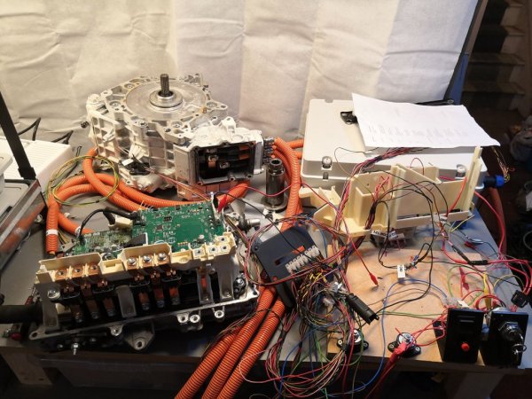
So, feeling like I have potentially burned my motor, and with my inverter being weird, I decide to pull everything out and rebuild it all on the bench for testing. This felt like a big job looking at it, but I actually had it all out and in the workshop within an hour, and reconnected with an updated version of my test rig (including key switch etc to replicate the cabin) in another hour and a half or so.

Then, with help via Skype from Jamie (@bigpie) I got to work trying to understand what was wrong with the inverter first. Going around the test points from the original build with a multimeter, it was clear something was wrong. Even with everything disconnected, my 5V lines were down at 4V and my -5V lines at -2.9.

Jamie suggested that maybe a MOSFET has blown closed and that is the next thing to test.

Next steps
In some ways I am quite glad to have the setup back on the bench. It has been hard to do much on the car with the dark coming in so early. And with the charger (yet to be unwrapped), port and cable having now arrived, I can also look at getting those working. While everything is out of the car I can use some of the daylight to finish up the hardware jobs I hadn't done yet: finally fitting the power steering pump and lines, and adding mounts for the cooling systems.

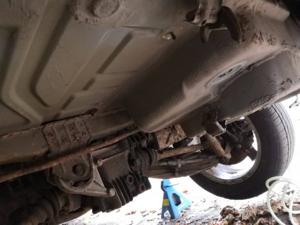
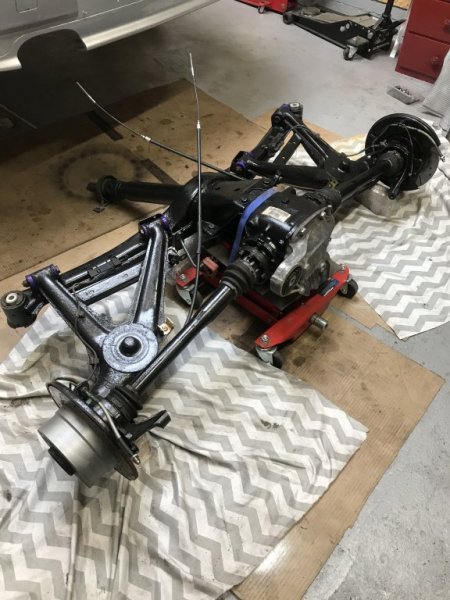
I also need to finish up a little bit of body work, removing the last of the rotten outer sills and tidying up my weld on the inner sill. Plus I need to drop the back axle and get the petrol tank out. Having looked at this job in more detail, I'm not convinced it's going to create a huge amount of space for more batteries. But we shall see. There's always the spare wheel space under the boot...

Then there are the modifications required to shink the battery box a bit to fit the charger in. In short, I am now resigned to the fact that there is a lot longer to go on this project than I thought. It's unlikely to be on the road this side of Christmas and frankly even Spring is starting to look ambitious.

On a brighter note, I did find a very cheap Outlander inverter...
 

Attachments

Tom Cheesewright

Zorg Guru (I)
Supporter
British Zeds
Joined
May 6, 2020
Points
90
Location
Manchester, UK
Model of Z
Z3
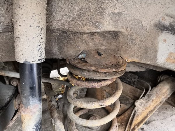
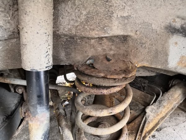
Question for you Z experts. Have searched the forum but can't find an answer: How have people fixed rusty rear spring tops? Took the back wheel arch liner off so that I could remove the remains of one of the rusty outer sills, and to make it easier to drop the rear subframe in order to remove the fuel tank. Realised once I cleaned all the mud off the top of the rear spring top that it has completely rusted through.

I can't replicate the curve it had before but I can weld in some plates on the diagonal to reinforce it. Do you think that will be OK for MOT/safety?
 

Attachments

t-tony

Zorg Expert (II)
Supporter
British Zeds
#ZedShed
Joined
Dec 31, 2013
Points
226
Location
Torksey Lock,Lincoln, England
Model of Z
E89 Z4 23i Auto
That should suffice Tom, just ensure you use steel at least as thick as the original and seam weld all joints.

Tony.
 

Tom Cheesewright

Zorg Guru (I)
Supporter
British Zeds
Joined
May 6, 2020
Points
90
Location
Manchester, UK
Model of Z
Z3
That should suffice Tom, just ensure you use steel at least as thick as the original and seam weld all joints.

Tony.
Thanks Tony. Glad to hear my instincts were correct! Have some new steel in and have bought a brake to get some nicer bends. First experiments have come out fairly well with new brackets for the power steering pump.
 

Tom Cheesewright

Zorg Guru (I)
Supporter
British Zeds
Joined
May 6, 2020
Points
90
Location
Manchester, UK
Model of Z
Z3
It turns out that the inverter board failing and me smoking some components (see last installment) was just the beginning of a week of technological disasters for me. My broadband router failed, wiping out a morning while I tried to cobble together a working arrangement until I could get hold of a replacement. In the middle of that, my web server (actually a virtual instance) failed. How? I still don't really know. But that wiped out another day. Then my home automation server failed, leaving my workshop without light or heating while I fixed that. For the rest of the house, I have been careful to make sure there are manual backups. But my workshop is a little more...experimental.

This all came at the worst possible moment work-wise, when I was absolutely snowed under. Suffice to say, I've been a little bit stressed. And as a result, not a lot has happened on the car. The downtime I have had has largely been spent blowing stuff up on Destiny 2 on my newly acquired Google Stadia setup (what can I say, it was free), or drinking wine (not the healthiest coping mechanism I know).

Anyway, most of the critical tech is working again (knock on wood), I've hit my various deadlines, and I can start to think about the car properly again. The challenge now is rebuilding my enthusiasm - challenging in the face of a few failures and also the worsening weather, which does not make going outside and crawling under a car very appealing.

Outlander inverter
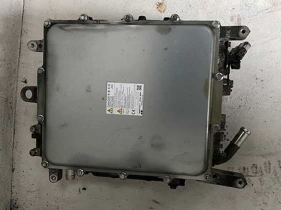
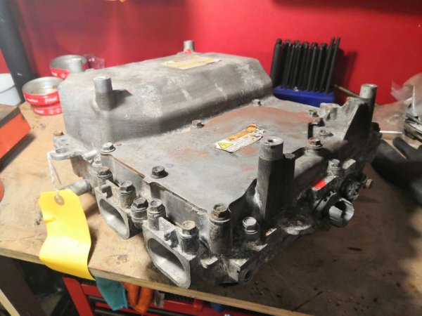
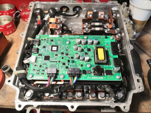
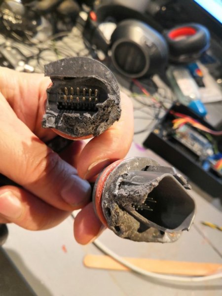
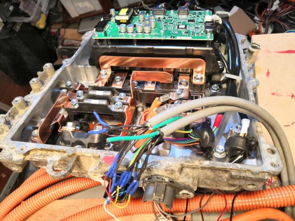
There are some things to do inside though. I've been working on getting the Outlander inverter working. (I'm updating the components page with information as I understand it). This unit looks to have been in a small engine bay fire. The low voltage connectors are a little bit...melty. But they still have all their pins and I successfully have the inverter turning on and spitting out CAN messages. I just don't understand them all yet. And early experiments to make it spin the wheels have been unsuccessful. I suspect some of the messages it is spitting out that I don't understand are errors.

outlander_inverter_1.jpgoutlander_inverter_2.jpgoutlander_inverter_connectors.jpgoutlander_phev_inverter_testing.jpg


SavvyCan
To help me with CAN diagnoses, I have bought an Arduino Due that I'm setting up for SavvyCan. But this is proving to be more challenging than expected. I can't get the sketch to run properly - it won't spit out anything to the serial terminal. So that needs some work as well. [update: this is now sorted]

BMS
Once I have that working, I plan to use it to get the BMS working properly. I had this set up wrong initially, with one CAN interface connecting to both the battery units and the rest of the car. Instead you should have two: one for the battery modules, and one for the rest of the vehicle.

With that in place, I want to get the charger running. There are some quirks to this as I need to have the BMS turn it on and off once the batteries hit target voltage. Hence focusing on the BMS first.

Safety box
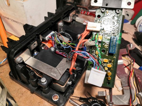
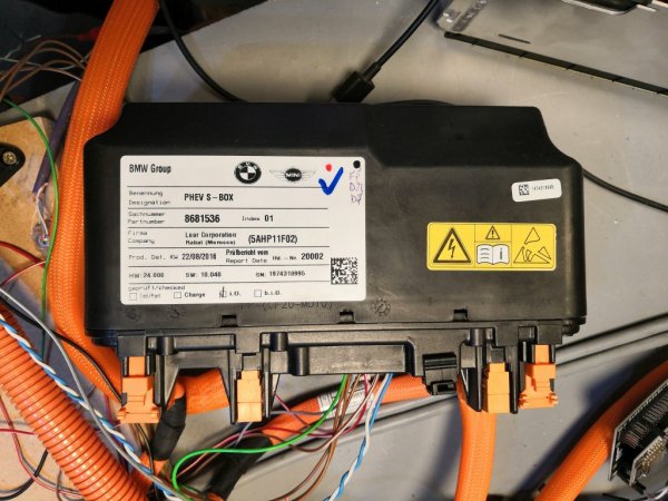
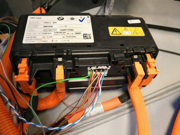
One thing I have done is some work on the salvaged Safety Box from the BMWE battery pack. Turns out this is a complete and very compact high voltage junction box. Others have already done the work decoding the CAN messages from it to get detailed voltage and current information. And it proved relatively trivial to rewire control of the pre-charge relay and contactors through the original connector, giving me a nicely compact alternative to my own, very large, junction box. So compact in fact that it will fit inside my battery box.

This solves two problems. First, it means that I don't need to worry about a safety disconnect: if the 12V is off, there is no way for high voltages to reach the battery box connections. Second, it frees up the space where the junction box sat so that the charger can go in its place, meaning I don't need to alter my battery box.

What I do need to do is sort out the design of the high voltage connector for the battery box, which proved not to work very well. That might be a project for this week in between work.
rewiring_s_box.jpg
bmw_phev_s_box.jpgbmw_phev_s_box_connectors.jpg


Inverter repairs
In the meantime, I have stripped down the inverter and removed the broken board. Damien was very reassuring, telling me it probably wasn't me who fried it and has kindly sent me a replacement. So, board number three (!) is off to the soldering whizz this week so that I can get my inverter back up and running.

I think I am probably going to stick with the Prius inverter rather than switch to the Outlander one. That is great for some experimentation but the Prius inverter gives me lots of flexibility and things like direct control of the contactors. If I switch away from that I will have to make up some new hardware for the BMS to control the contactors and that just feels unnecessary.

Next steps
Still lots of work to do on the car itself, including welding up the rusty rear spring mount. Some new steel has arrived from Frost restorations for that, and I have also invested in a brake for folding brackets. These will be used for the repair patches for the spring mount but also for brackets for the power steering pump (which I have decided to relocate, based on advice from my daughter - she suggested the new location weeks ago and I have finally listened) and the heater, which I might as well get wired up while I'm at it.

I did get some way towards getting the fuel tank out, removing the spare wheel carrier (too rusty to bother putting back in place), and loosening some bolts. But I couldn't get the bolts connecting the propshaft to the diff to shift. I hope to have another go at that today.

I also plan to take an angle grinder to the engine bay and get rid of some of the old brackets that are in the way. Past the point of no return now...
rusted_spring_mount.jpg
spare_wheel_space.jpg
 

ukcerb

Regular Member
Joined
Nov 7, 2017
Points
20
did get some way towards getting the fuel tank out, removing the spare wheel carrier (too rusty to bother putting back in place), and loosening some bolts. But I couldn't get the bolts connecting the propshaft to the diff to shift. I hope to have another go at that today.]

Keep up the good work, I wish I had your electrical knowledge to take on a project like this.
I can offer some advice on getting the rear subframe out however. If you can’t undo the prop to diff bolts then undo the central prop connection (a large pair of grips will work fine) and the support bracket and when you remove the beam carrier assembly the prop will slide apart.
 

Attachments

Tom Cheesewright

Zorg Guru (I)
Supporter
British Zeds
Joined
May 6, 2020
Points
90
Location
Manchester, UK
Model of Z
Z3
I can offer some advice on getting the rear subframe out however. If you can’t undo the prop to diff bolts then undo the central prop connection (a large pair of grips will work fine) and the support bracket and when you remove the beam carrier assembly the prop will slide apart.
Fantastic - I did wonder if there was another way to do it. That should make life much easier. Thanks!

The electrics I'm very much learning as I go along. I did study it at university as part of a broader engineering degree but that feels like a very long time ago when I'm hooking up 200 volts and wincing as I throw the switch!

If you're interested, Damien Maguire's videos are a great place to start (and very amusing). https://www.youtube.com/c/Evbmw
 

ukcerb

Regular Member
Joined
Nov 7, 2017
Points
20
Fantastic - I did wonder if there was another way to do it. That should make life much easier. Thanks!

The electrics I'm very much learning as I go along. I did study it at university as part of a broader engineering degree but that feels like a very long time ago when I'm hooking up 200 volts and wincing as I throw the switch!

If you're interested, Damien Maguire's videos are a great place to start (and very amusing). https://www.youtube.com/c/Evbmw
Thanks for the link I’ll have a look at those.
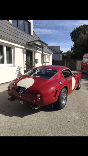
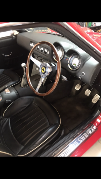
I noticed you will be doing a Tribute build on this at the appropriate time. I had priced up to do an EV conversion but parts alone came to over £30k (150 mile range 400 torque) so holding fire for now but it will happen at some point as we near the 2030 deadline.
I’ve done a couple of Tribute builds now so happy to offer any advice when the time comes.
 

Attachments

ukcerb

Regular Member
Joined
Nov 7, 2017
Points
20
That's gorgeous!

Definitely doing the Tribute build. Hoping to do two in the end. I've learned so much about the EVs in the last few months that I don't feel I can stop at one. Maybe a summer and a winter car! Will no doubt be tapping you up for help.
Thanks, it’s the 250 but don’t think they do this one anymore which is a shame. The new dash is all electronic gauges too so probably not impossible to keep the look for EV but that’s obviously your area of expertise.
While you have the back axle out it would be worth narrowing the track so you can fit deeper dish wheels if that’s the look you wanted? The Z4 hubs would narrow the track by about 22mm each side or if you want more (over 40mm each side) a company called Grassbank do a conversion kit using different callipers and hydraulic handbrake. I’ve done a couple of these for other people and they’re not hard to fit for a man of your skills.
 

Attachments

GZed

Zorg Guru (I)
British Zeds
Joined
Jun 28, 2018
Points
95
Location
Shrewsbury, Shropshire
Model of Z
Z3 2.8 Prefacelift
“...I did get some way towards getting the fuel tank out...”
Hi Tom. Re the fuel tank, it’s plastic, so as you’re not going to need it any more it might be easy just to slice it into sections with a hacksaw or sharp bread knife. I know you’ve got other reasons for removing the rear beam but for now if you just want to remove the tank to take measurements of available space etc this would do it. {Obviously be aware of explosion risks from petrol vapours - hand tools when cutting , don’t create sparks...}
 

IainP

Zorg Guru (II)
British Zeds
Joined
Feb 20, 2019
Points
119
Location
Out of my Tree, North of Perth, Scotland
Model of Z
1.9
Don't cut a tank.
Having removed a few in my time it's surprising how much fuel is still contained in an "empty" tank.

This thread is fascinating, I don't understand half of it, but I absolutely love it.

Regarding that weld repair, zap it with a wire brush in a grinder, then clean the metal with a flap disc. That'll show you how far back you may have to cut.
If it just stays as that crack, and you have any copper sheet/plate/heat sink, you can place that behind the crack and stitch weld it closed. Don't try and weld all in one go, pulse it, one second weld, one second off, move so as to overlap the previous weld. Essentially it's a series of overlapping spot welds..
If you do have to piece a bit in, the same technique puts less distortion into thin metal.
From your other weld pictures, as I think you've already surmised, something wasn't right.
I think you've already checked your earth, but it's worth opening the machine and shortening the cable to where it enters the machine, tends to fray internally there. If it's a dinse connector I'd shorten it about 6-10cm, that's where all the fraying occurs.
I also find the www.metalstore.co.uk a lot cheaper than some of the other online suppliers.

Iain
 
Top