Z3(00S) - EV project

IainP

Zorg Guru (II)
British Zeds
Joined
Feb 20, 2019
Points
119
Location
Out of my Tree, North of Perth, Scotland
Model of Z
1.9
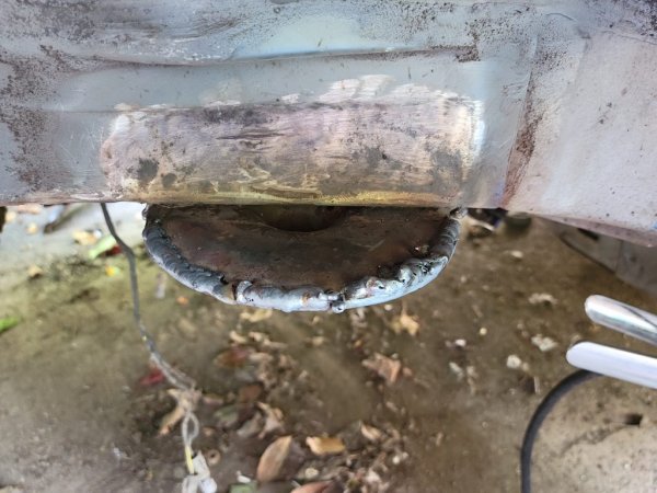
Just to show it’s not that bad.
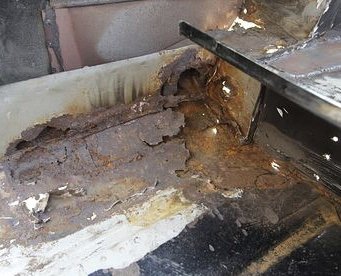
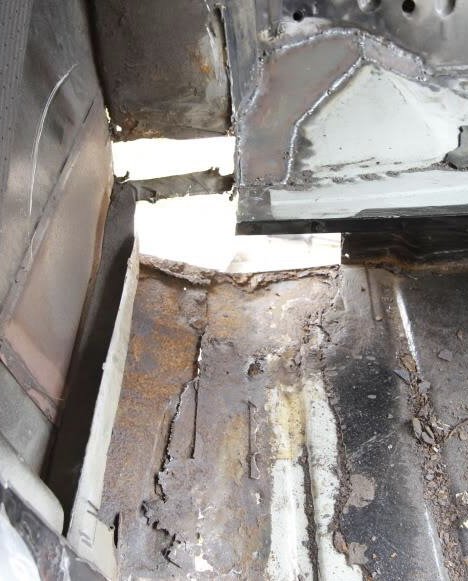
This was 3 years after a Mini was professionally restored by sort of welding over the rust. When we took the carpet out half the floor came with it.
B7F52651-56A9-4603-9B2C-04DA5A12283B.jpeg
much measuring, the some cutting to leave this
740D63C2-EE0D-47EF-834F-38199F5F0B50.jpeg
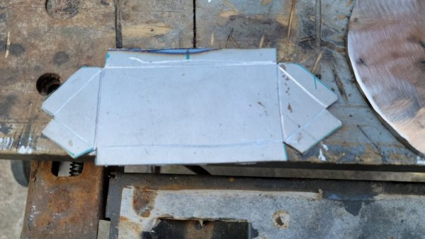
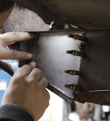
Then matching the lines we’d scribes in
BB9E00B6-0504-463A-ABB0-0A8779292F56.jpeg
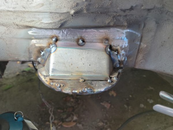
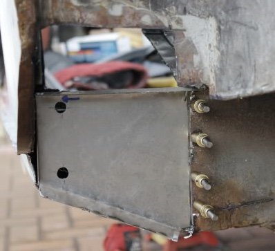
the Cleco pins allow the panel to come on and off exactly. Those holes have to bang on, that’s where the rear beam bolts. Repair panels are available, but we had no reference points to weld them to.
Spot the error.
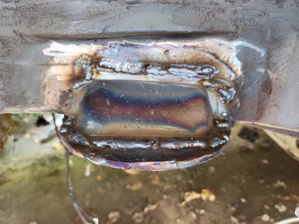
The flange goes on the inside of the panel , but we didn’t leave a gap to fit the weld in, meant extra work with a flap disc.4FC94A15-9C51-4743-8277-9C0768EEB3A6.jpeg

When you weld, don’t try and do it as one seam weld, pulse it, one second, off, move, one second weld. Like a row ov overlapping coins. Puts less heat in, so less distortion, less weld height, easier clean up. Use a flap disc, Not a grinding disc, they’re slow and produce loads of heat.
 

Tom Cheesewright

Zorg Guru (I)
Supporter
British Zeds
Joined
May 6, 2020
Points
90
Location
Manchester, UK
Model of Z
Z3
Thank you Iain. That's really helpful and hugely appreciated.

Will get the interior out (again) this weekend so that I can get a look from the top side and get it cut out. At least the fuel tank is out now.

Will get the calipers on the metal to work out the thickness unless anyone knows what that bit of body is? Think I only have 1mm sheet and some thick plate in at the moment so may need to go shopping.
 

Tom Cheesewright

Zorg Guru (I)
Supporter
British Zeds
Joined
May 6, 2020
Points
90
Location
Manchester, UK
Model of Z
Z3
Pm me your address I’ll send you a joggler, the Cleco and pliers. Most panels are 1mm or 1.2mm. I can recommend https://www.themetalstore.co.uk
if you don’t have any local suppliers.
I have a couple things to weld on Sunday, will try and do a couple of test pieces to show you.
Doh! Only just seen this Iain. Thank you so much. I bought a cheap joggler (which didn't turn out to be much use) but I've muddled on through and am getting there as you'll see from the update shortly.
 

Tom Cheesewright

Zorg Guru (I)
Supporter
British Zeds
Joined
May 6, 2020
Points
90
Location
Manchester, UK
Model of Z
Z3
Time for another monster update as it has been over a month since the last one. What have I done?

Rear axle assembly
Getting this apart proved a ballache. Lots of rusted nuts & bolts - was glad of new impact wrench. Brake lines were the worst. I ended up cutting most of these off. The calipers were pretty shot too. One was maybe rescuable but I decided to get a used pair off eBay and refurb them with kits for new seals and pistons etc. I have all the parts and kit to redo the lines and some new flexis have arrived.

I didn't completely strip this all down but everything has been cleaned up with a wire wheel and treated to a coat of black paint. It's not good and I will replace everything at some point. But it's OK.

Fuel tank
With the rear axle out I could finally remove the fuel tank completely. I ended up having to cut a chunk out of the tank so that I could get to the allen head bolts for the rear axle, so it was completely empty. Took a lot of wiggling and pulling to remove it though. Nothing really salvageable. Fuel pump was a mess.

Rear arches
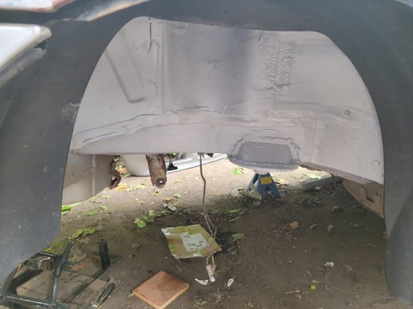
Part of the reason for wanting to get the fuel tank out was so that I could confidently weld around that area. Driver's side rear strut top was rusted out at its corner, as is the spring mount on both sides.

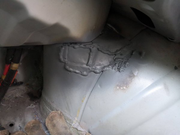
Fixing the strut top meant stripping the trim from the rear of the cabin and the boot, and a lot of patient grinding to uncover the true extent of the rust, which just kept growing. I have limited fabrication tools so the repair had to be made up of lots of small pieces of metal welded in progressively. It's not beautiful but it is structurally sound and that will have to do for now. And no-one is going to notice once it is covered in seam sealer. For now it is covered in a couple of layers of primer while I see to the spring mounts.


In an ideal world I would replace these with some off the shelf repair panels, but I can't find any. So, I'm making up some over-engineered repair pieces. 3mm steel rings to reinforce the rusted parts and a 1mm folded steel brace on the top. These are largely measured up and templated and when I get time I'll get them cut out and welded in. Then the back axle can start to go back in, along with the refurbed brakes etc.

Power Steering
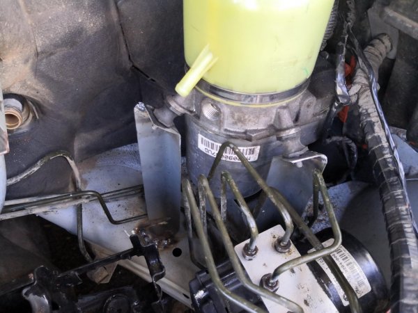
I’ve finally welded in the brackets for the Zafira power steering pump. This was delayed by stuck connectors to the ABS pump – I needed to move some of the brake pipes to access the space where I wanted to weld. I managed to get all but one undone without shredding anything with the liberal application of WD-40 over a few days. This created enough space to grind away the paint with my new finger sander and weld in the three brackets.

In retrospect, I wish I had made them from slightly thicker steel (I think it’s 0.75mm), but with the three of them it should be fine. If needs be, I can brace one of them off the heater mounts (below).

I have been hunting around for connectors to replace the stock BMW ones for ages and have even bought a few bits. But I’ve now found an online service who will make up a custom hose with the right fittings for very sensible money, so I’m just going to do that. The old BMW cooling loop was heavily corroded, so I’ll replace this with a little oil cooler on the return line.

Heating
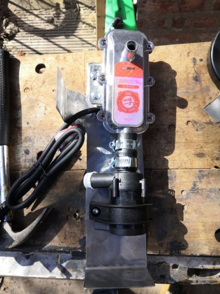
I bought and modified an AC car pre-heater to remove the pump so that it can run on DC. The full 350V of my main pack may be a little much but we shall see. There is now an external 12V DC pump to keep water flowing through it rather faster than I think the internal pump would have managed so that should balance it out.

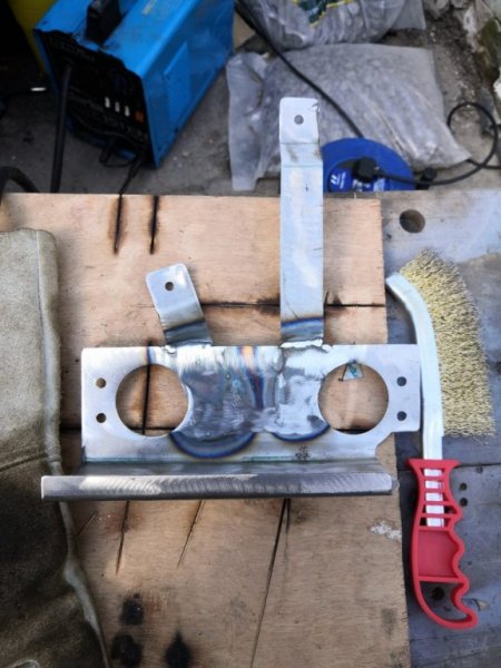
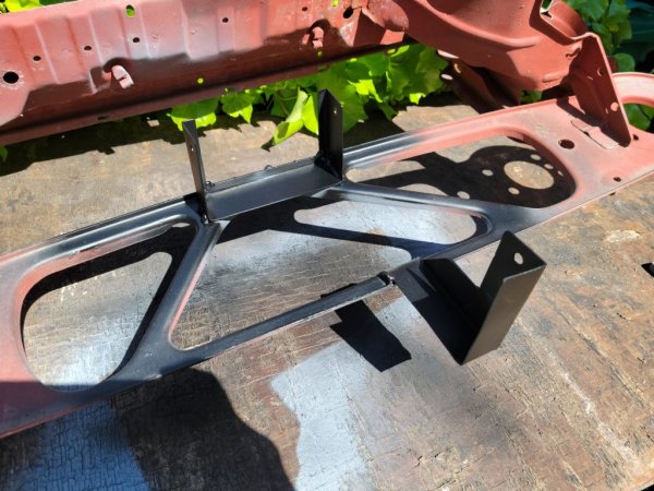
I fabricated a bracket to hold the heater and pump next to the bulkhead that will be welded to the frame and a former solenoid mount that protrudes from the bulkhead.

I’ll need some sort of filler arrangement. And I need to make up a pipe to take an in-line temperature sensor that I picked up off eBay (irritating 1/8NPT thread that you can’t model in Fusion360). This will connect to an Arduino that will drive a contactor on the live line – a feed from the old A/C connector on the inverter. Plan is to take a simple on/off signal from the wiring from the old solenoid valve that I believe must have routed water from the engine through the heating loop when the heating was turned on in the cabin.

Just waiting on paint to dry on the back of this before it can be welded in, as this won’t be accessible once it is.

Inverter & charger mounts
I’ve cut off my inverter and charger mounts that were welded to the top of the engine mounts. This is because I wasn’t particularly happy with them after lots of modifications, and because I now have lots more space to play with. The charger is a lot smaller than the old high voltage junction box (replaced by the BMW ‘safety box’ now integrated in to the battery box). Plan is to make up some new mounts with fresh steel so that the inverter can be rotated through 90 degrees. This will create more space for the battery box so that getting the lid on and off isn’t a total PITA.

This should also create some more space for the cooling systems, both oil (for the motor) and water (charger and inverter).


Work on the car continues to be held up by various things: building work, earning money, actually seeing my family, snow(!!). And unfortunately, the workshop I hoped I would have by now has fallen through. I’ve been on a big hunt around my local area to find something suitable, but nothing is available at the moment. Still, clear progress being made. Might actually finish it this year…

In the meantime I'm on the look out for a cheap 3D scanner. Might have to buy a second hand iPhone as they seem to be pretty capable. I want to be able to plan things out better in CAD before I do this again, or redo things on this project. And making mock-ups of complex 3D shapes with all their oddly spaced flanges and mounting brackets is a PITA.
 

Attachments

Tom Cheesewright

Zorg Guru (I)
Supporter
British Zeds
Joined
May 6, 2020
Points
90
Location
Manchester, UK
Model of Z
Z3
(This might be best read on my blog - I've reposted all the content here but having trouble adding in-line images so they're all at the bottom. You can find it here: https://projects.tomcheesewright.com/2021/06/06/monster-update/)

You know how it is with big projects: life gets in the way. So I won’t bore you with the details. But, things are flying again on the Z300 EV project. In bullets first just give me an agenda for my own post:
  • All the welding on the rear quarters is done
  • All the remaining mounts and brackets are finished
  • The motor cooling loop is in
  • The inverter/charger cooling loop is largely done
  • I’ve started wiring up both HV and 12V again
This is why I called this a monster update! (Though I said the same about the last one).

To break things down in a bit more detail:

Rear Quarters
If you have been following this project, you will know that I bought an absolute lemon that required a lot more welding than I planned for. Anyway, that is all now done. Is it pretty? No. Do I think it will get through an MOT? Yes.

The main problem areas were the top mounts for the rear springs, and the strut top for the offside rear. I welded that up a while back and wasn’t very happy with it at the time. But when I came back to it with a bit of distance I decided that though it was far from pretty, it was actually very solid.

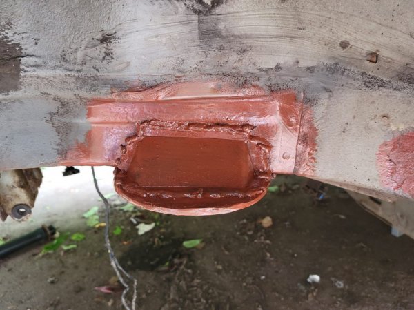
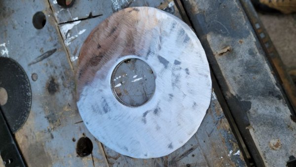
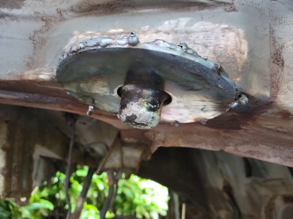
The spring mounts required some serious fabrication though. Two parts had largely dissolved. The mount itself, a disc of metal with a round locating nub in the middle. And the cover/brace piece that sits between the disc and the upright section of the car body. You can probably make better sense of this from the photos.

I couldn’t find repair panels for these parts so I decided to half repair, half make my own. I cut some 130mm discs out of 3mm steel, and then drilled large holes in the centre so that the locating nubs – which hadn’t rusted – would protrude through. This means there is less ‘nub’ than there would have been originally, but having tested it with a spring, they still seem to locate fine. The springs will sit a couple of millimetres lower as a result – and perhaps the car a little higher – but I don’t think anyone is going to notice.

My neighbour asked if I was going to get these laser cut. “Um, no, I’m doing it with an angle grinder.” Next time, I will get them made by someone who can draw a circle.

I couldn’t get the discs to locate perfectly flat against the car tub, so had to put some chunky welds in, in places. But I think the weight should be fairly well distributed. And they seem to be at the same angle as what was left of the original parts. I may have some issue when it comes to reinstall the rear suspension assembly, but we shall see.

For the cover/brace, I used the classic CAD (cardboard aided design) approach and then cut and folded some steel to match the pattern. Can’t remember the thickness off the top of my head (I’m writing this after a couple of beers) but they are very stiff. Maybe 1mm? I partially seam welded these in so they add a lot of rigidity.

The whole lot was then coated in red oxide primer, then paint, then seam sealer, then a coat of stone chip for good measure. If I’ve done it wrong, it will be easier to scrap the car than get all that crap off. And TBH, if this fails its MOT on structural issues, that is what I will do. The car owes me maybe £300 and I can get that back by selling off parts. So I will just treat this as a training exercise/development mule, strip out the bits I’ve added and move them to a more solid donor.

Mounts and Brackets
In the last update I said I needed to redo the mounting brackets for the inverter and charger. I didn’t mention that I still needed to make mounts for:
  • The oil pump (for motor cooling)
  • The oil reservoir
  • The oil cooler
  • The water pump (for inverter and charger cooling)
  • The radiator/reservoir
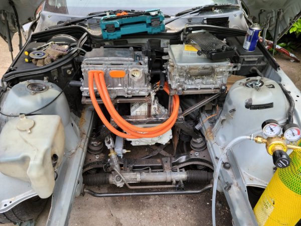
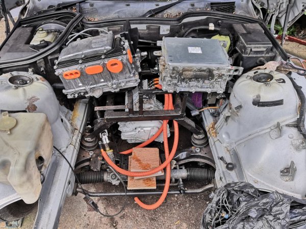
Starting with the big parts, I went and bought some new 20mm box section with fairly thick walls (1.5mm again I think) and started fabbing up some new mounts to sit across the top of the engine bay, close to the firewall. The inverter sits in front of the driver and the charger on the passenger side. With a bit of fettling, these now sit nicely lined up and leave plenty of room to get into the battery box. They also leave room for all the cooling bits.

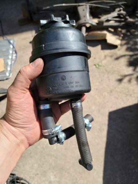
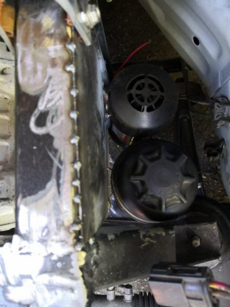
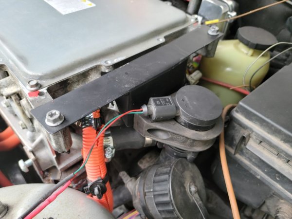
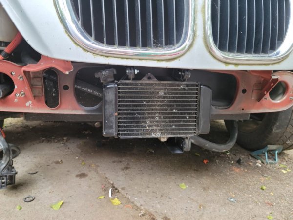
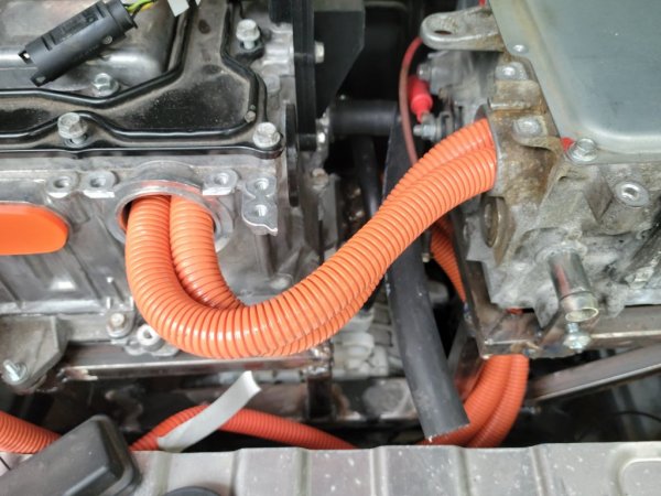
I made up a bracket to hold the oil cooler down to the left of the motor on the engine bay image. It’s horizontal, which is a bit weird. And the clearance to the cross member isn’t amazing. But it doesn’t seem to touch it under pressure. And it means it can act as a giant U bend, taking the warm oil out of the motor and feeding it back into the reservoir. For this, I have re-used the old ATF reservoir from the old power steering system.

The reservoir and the oil pump are mounted on a plate to the right of the motor on the picture below. This is welded to the frame that carries the charger, and bolted to the transmission adaptor plate as well. I should cut away the excess on the plate but I decided to leave it for now in case anything else needed mounting there.

From the pump, the oil goes through a right angle bend then up and over and into the top of the motor. Don’t have any pics of this pipe yet.

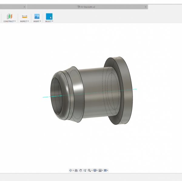
That pretty much completes the oil cooling loop. I just need to make a plug to block off the secondary outlet on the bottom of the motor. I’m going to 3D print this from PETG. It’s fairly chemical resistant and I don’t foresee the motor temperature getting very high. If it does, I’ll get one machined out of brass or something.

The water pump is now mounted off the side of the charger on another bracket I made up. Could do with a bit of a trim and the paint isn’t great but I’m focused on function for now.

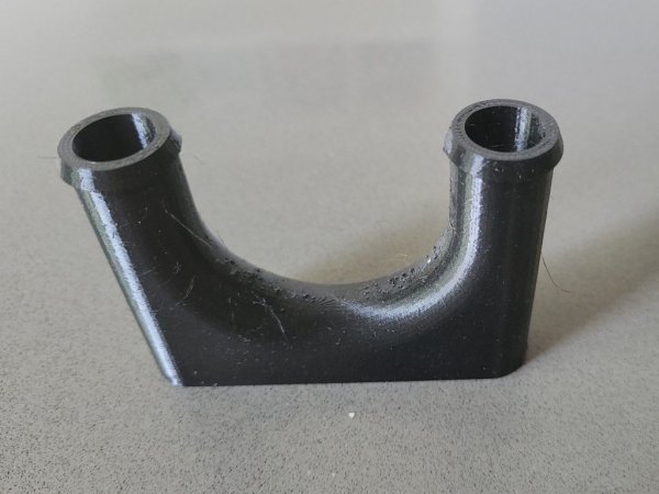
The pump runs water through the charger, then into the inverter via a bit of a dogleg using another 3D printed part. Designing tubes for printing is a ballache, especially if you are trying to avoid using support materials. Hence the funny shape.

From the inverter, the coolant runs down to the little motorbike radiator, now mounted in front of the battery box. Lots of air flow and well out of the way. These brackets are welded to the old front valance (and yes, I will give the whole thing a coat of paint eventually).

Cooling loops
With all the components in place, adding the cooling loops is ‘simply’ a matter of running the right sized hoses, elbow pieces, and lots of jubilee clamps. These are proving to be another ballache, especially in tight spaces. I think the jumbo pack of jubilee clamps I got from a discount supermarket about ten years ago maybe aren’t great quality. Who knew?

Anyway, most of the hoses are now in apart from the last links to the radiator, and the dogleg between inverter and charger (I snapped the first 3D printed part so currently reprinting with thicker walls). I’m looking forward to testing these, not least because no-one has mapped the resistance on the thermistor in the motor I’m using yet, so I won’t be able to get accurate temperature readouts until I do.

HV Wiring
Finally on this monster update, wiring. The HV wiring is largely done, with the exception of the heater. I still need to find space for a box to carry an Arduino, or similar, and contactor, to provide me with sensing and switching for the water heater and pump. And I haven’t yet made up a part to integrate the temperature sensor into the heating loop, though I now have an idea for how to do this.

The last wires I had to make up on the HV side were to carry DC from the inverter auxiliary connection to the charger. Using the same 35mm2 cable for this and it’s just two short runs. I still need to make up some shrouds for the ends of these to keep the inverter and charger better sealed from moisture. Tried a couple of designs so far but nothing I’m happy with. Don’t really want to just dump a load of silicone in there.

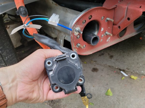
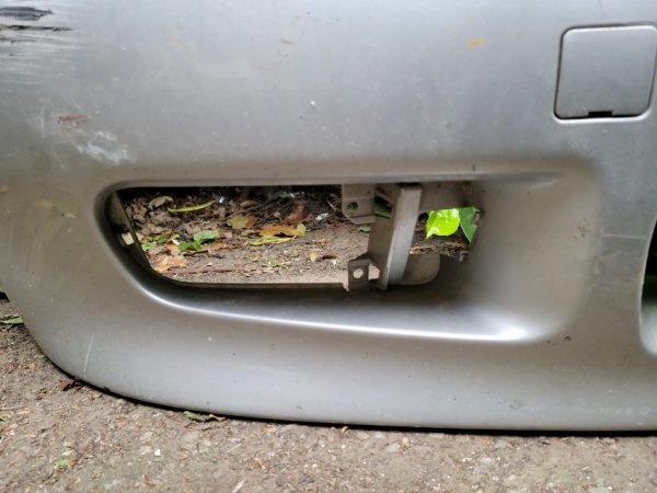
I have decided to mount the charging port in the front bumper for now, in one of the blanked off fog light spaces. It’ll get a little mucky but it’s not like it’s going to be there for long, or like I’m going to be travelling long distances on 8kwh. It just means I don’t need to extend any of the cables. When I do the rebody, I’ll put it somewhere proper.

12V Wiring
Absolutely last for this update is the 12V wiring. This is time consuming. And right now, a mess. I’m having to strip back some of the loom I thought was pretty finished in order to get the charger connections in neatly, and also because I have come to the conclusion the stubs on my CAN bus wiring were too long. Very grateful for my gas soldering iron right now, so I can cut and join things in situ.

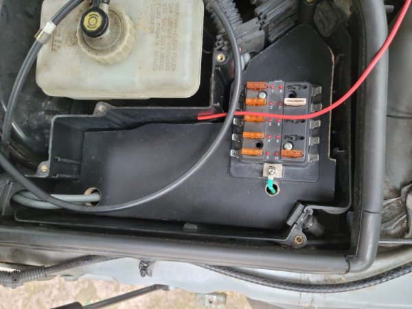
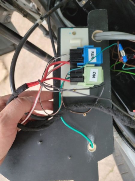
I’ve done a couple of things to try and make it all a bit neater. First, I’ve ditched the plastic insides of the sealed ECU box on the driver’s side of the engine bay and replaced them with a flat MDF shelf. This will allow me to lay out my fuse boxes and relays nice and neatly, and hide away any unused wires from the original loom. I stupidly painted this before making all the final holes so I will have to pull it out and repaint it at some point.

The second thing I’ve done is start to re-introduce some of the original plastic and rubber wire management pieces, including the shelf/conduit that bolts in along firewall. This needed some trimming in order to fit, but it should keep things nice and tidy.

I don’t want to start wrapping anything just yet until I know it all works. And the AMPSeal connector on my inverter is a total mess, as are the connections to the motor for temperature and position. Lots of work still to do here.

Progress
Nonetheless, it feels like the project has taken massive steps in the last week and I’m really pleased.

Next steps are to finish reassembling the back end. I can’t find the anti-roll bar mounts at the moment (they must be somewhere – I know I painted them) and I’m waiting for replacement strut tops as I managed to throw one away. I still need to redo the two sets of flexi brake lines on the back end, as well as the hard lines that mount on the back axle assembly. First attempt at bending and flaring brake pipes so that will be fun. And I haven’t yet used the brake caliper rebuild kits I bought maybe six months ago, though the rusty old calipers are now looking shiny in a coat of paint.

At the front end, I still need to get a high pressure line made up to connect up the PAS pump, and putting that in will require taking everything else out. When I do that, I’ll give some of the brackets a coat of paint and maybe tidy up the engine bay a bit. Really pleased with the Hycote stone ship paint I picked up at the local motor factors so might get some more of that and do the sills as well.

There’s the plumbing to finish and test. And the wiring. So much wiring.

Then it’s the scary bit: getting the laptop out and trying to make it all work again. Thinking I might add an Arduino Mega into the CAN bus loop and run a USB cable into the cabin to make testing easier.

But as Ed China says, that’s a job for another day.
mu1.jpgmu2.jpgmu3.jpgmu3.pngmu4.jpgmu5.jpgmu6.jpgmu7.jpgmu8.jpgmu9.jpgmu10.jpgmu11.jpgmu12.jpgmu14.jpgmu15.jpegmu16.jpgmu17.jpgmu18.jpgmu19.jpgmu20.jpgmu21.jpgmu22.jpg
 

mrscalex

Zorg Guru (IV)
Supporter
British Zeds
3rd Party Trader
Joined
Jun 10, 2016
Points
165
Location
Swindon & Swansea
Just catching up with whole thread here. Fascinating.

My view on those rear spring top plate ‘hats’ is this. They are not structural. They are way too thin and add little to other much chunkier bits of metal in the area. I think they are purely for running off water that would otherwise land on a very flat surface.

I had one made up by a panel beater using the old one as a template.

My welder was also the MOT tester. A very strict man who always gives me a load of advisories I wouldn’t get anywhere else. So not prone to leniency... he said for him they are not structural and he wouldn’t have failed the car anyway with the old rotten one...
 

Tom Cheesewright

Zorg Guru (I)
Supporter
British Zeds
Joined
May 6, 2020
Points
90
Location
Manchester, UK
Model of Z
Z3
Just catching up with whole thread here. Fascinating.

My view on those rear spring top plate ‘hats’ is this. They are not structural. They are way too thin and add little to other much chunkier bits of metal in the area. I think they are purely for running off water that would otherwise land on a very flat surface.

I had one made up by a panel beater using the old one as a template.

My welder was also the MOT tester. A very strict man who always gives me a load of advisories I wouldn’t get anywhere else. So not prone to leniency... he said for him they are not structural and he wouldn’t have failed the car anyway with the old rotten one...
Interesting! Well mine are now nice and chunky - a little bit of overengineering shouldn't hurt.
 

Tom Cheesewright

Zorg Guru (I)
Supporter
British Zeds
Joined
May 6, 2020
Points
90
Location
Manchester, UK
Model of Z
Z3
BUZZING!

It works. It bloody works.

Video here: https://projects.tomcheesewright.com/wp-content/uploads/2021/07/20210704_091221.mp4

After a frustrating few days with it sort-of working, and some minor mishaps (I shorted something on an unshielded 12v connection – but everything seems to have survived). A firmware downgrade (5.05 to 4.96 if you’re interested) has fixed everything. The wheels spin like a dervish now and the motor makes an absolutely wicked noise. My homebrew coupler seems to be doing a decent job too, much to my surprise and delight. I was expecting a lot of vibration and clanking! The clicking you can hear in the video is a loose brake flexi pipe clacking against the wheel (whoops).

Needless to say, my daughter and I are absolutely buzzing. We’ve spent the whole day talking about the all the fun cosmetic bits that now feel much closer.

What’s been done since the last update?

  • Wiring is all finished apart from the fact I need to take the last chockblock out. I’m now confident I have the resolver wired in correctly
    chock_block.jpg
  • I’ve tried and failed to calibrate the temperature sensors in the motor by taking resistance readings while pumping through oil heated to a known temperature (and probably ruining a rice cooker in the process). I just couldn’t get stable enough temperature control, and it turns out my oil pump is massively overpowered for the purpose, emptying the rice cooker in just a few seconds.
    calibration.jpeg
  • I’ve torqued up all the front end bolts, and finished refitting the propshaft
  • I’ve completed the refurb on the rear calipers
  • The charge port has been installed in the front bumper
    charge_port.jpg
  • Discovered the only problem with the electric hood is a flaky switch
  • I’ve changed out the Prius control board (number four?) as I was getting some wonky readings. Turns out this was probably the firmware, but hey, it works now.
  • In the process, I managed to put a hole in the IDC cable that connects the board to the outside world and had to make up another one to keep testing while I waited for a replacement. You see! It’s good that I was still hoarding three old floppy disk cables!
idc.jpeg

idc_2.jpeg


What still needs to be done before I can take it for MOT? This is checklist for me as much as anything.

Battery box
I need to mount the high voltage switch box and the BMS properly in the battery box. This will be done with a thick sheet of MDF for now, with some holes drilled so that it can be bolted down to the protruding screws below which have threaded, socketed heads (scavenged from the original BMW packs).

I then need to waterproof the box a bit better, line the lid, and pack it with some silica gel to pick up any condensation.

HV disconnect
I need to add a safety disconnect for the HV, as at the moment if the contactors welded themselves shut (something I’ve already done to one set) there would be no way to disconnect the battery without a spanner. Still deciding which model to go for, or whether to make one (they are damned expensive – £100-150 for some plastic and copper so started sketching out a design below. This is flawed but a start). This will be bolted on to the side of the battery box.
safetydisconnect.png


Relocate the radiator
Dumbass here forgot about gravity, so unless I’m going to seal up the steam pipes on the radiator and add a header tank, I need to move the radiator.
radiator.jpg

For now it will get mounted where I was originally planning, in front of the charger and inverter. But first, I need to…

Lower the charger
Somehow I screwed up my measurements and the charger sits fractionally too high now, meaning the bonnet doesn’t shut all the way.
bonnet.jpg

There is a relatively straightforward fix which means cutting its mounting frame off, trimming it to fit around the ABS pump, lopping an inch of the legs that support it, then welding it back in again. I think that should fix the problem.
charger_mount.jpg

While I have all this out, I’ll give it all a coat of paint. I might clean up the engine bay a bit at the same time. Not to its final state but a bit more presentable.

Hook up the brake booster
I’ve bought a brake booster pump controller from Johannes at OpenInverter, which takes a reading from a standard Bosch pressure sensor and turns the brake booster pump on and off as needed so that it doesn’t have to run all the time. I’ve designed and 3D printed a case for this and mounted it in my fuse enclosure.
boost_controller.jpg

boost_controller_2.jpg

I’ve also cut the various pipes to length to connect the sensor, pump, reservoir and booster. Now I just need to put it all together and work out the wiring of the sensor (I can’t find a reliable pinout, though I have had it working before). Unfortunately, the T-adapter I bought that connects the different hose sizes of the various components snapped under the bending pressure of the stiff hose (ooh-er), so I need a better arrangement.
vacuum_hose.jpg


Make new rear brake lines
I made up new rear brake lines before I refitted the rear axle. Problem: I misunderstood their routing and made them the wrong shape. So need to make up some new ones. I have plenty of pipe and fittings so no biggie. Just need to get around to it.

Refit rear calipers
Calipers are ready to go on and the flexi lines that connect them have been replaced. Problem? I’ve lost the bolts that hold them on somewhere. Need to scour the workshop or get on eBay. Once I have these on I can add some new fluid and bleed the system.

Check ABS works
I suspect the ABS/ASC system may want some communication from the ECU. Hard to be sure when the brake system is in pieces. Once it is all reassembled, we shall see.

Complete rear axle fitting
I had to destroy four allen head bolts to remove the read axle assembly. The first replacements I ordered based on a recommendation from the forums were the wrong size. Second set fit much better. Need to get these in and then get everything torqued up.

Change windscreen wiper blades
Little job, but necessary!

Turn off dash error lights
Various error lights on due to lack of ECU/brake system in pieces. This will take some diagnosis. Still not sure which lights are controlled by CANbus and which (most, I think) by direct 12v signals. I’m hoping that once the brakes are all reinstalled, all the brake related errors go away, but I suspect the ABS may need a little more than that. Then it’s the EML, which I don’t *think* is an MOT failure, but want to fix.
dash_lights.jpg


Make charging work
Not strictly necessary for MOT but I don’t want to run out of juice on the way there. This will be a whole post in itself. Right now, I can’t seem to get either the old car CANbus, or the new EV stuff talking. Even though it worked fine on the bench.

Reroute oil cooling pipework
There are two outlets on the bottom of the motor for oil. I picked the wrong one. So now need to relocate my oil cooler and replumb the system – slightly complicated by this needing different-sized hoses and hence me needing a different-sized connector on my oil cooler. Unless I bodge it together…

Per the note at the start about calibration, I could also do with a controller for the oil pump. This is likely to be as simple as possible for now. Adding in a way to get an external temperature probe in for calibration wouldn’t be a bad idea – maybe using the spare outlet.

Also, when I was trying to calibrate, it leaked like a sieve. So I need to check gaskets and nip up some bolts.
leak.jpeg


Seal charging port
The back of my charging port is currently more open than I would like. Need to remove it to finish the design I have for a cowling that will fit the rubber boot currently on the cable.

Fix power steering return
My homebrew return line for the power steering fouled the bottom of the battery box. I’ve trimmed the battery box support bar but I still need something a bit lower profile.

Tidy wiring and plumbing
My HV wiring all needs securing so it doesn’t flap around, the 12V wiring all needs wrapping in TESA tape, the fuse box needs a tidy up, and the plumbing needs securing as well.

Fix my crap repair
One of the first repairs I did on the car was on the inside front of the sill behind the offside front wheel. It’s crap and needs redoing. I don’t think it’s structural but I don’t need to give the testers anything else to complain about.

Aaaand, that’s it…or is it?
OK, I’ve probably forgotten loads of stuff. I’ve printed off an MOT checklist to help me. The car will almost certainly need a new set of tyres. Obviously I will need to add coolant and check for leaks. And check all the lights work – after the loom has been banging around for a while, some new bulbs will probably be needed.

But I have a list. And I have a deadline. Announcing when I’m going on holiday probably isn’t smart. But let’s just say I have a holiday booked. And I want to get the car MOT’d before we go.
 

mrscalex

Zorg Guru (IV)
Supporter
British Zeds
3rd Party Trader
Joined
Jun 10, 2016
Points
165
Location
Swindon & Swansea
Wow some project. And what a result getting it running. Congratulations.

I believe the EML light is now in the MOT as of 2-3 years ago. @t-tony or @Stevo7682 may be able to confirm.
 

Stevo7682

Zorg Expert (I)
Supporter
The M44 Massive
Scottish Zeds
Joined
Apr 1, 2016
Points
208
Location
Maybole , South Ayrshire
Model of Z
Z3 Individual Dakar / Orinoco Individual
Yes this is true.
There may be a way round it with having the ev conversion but I am on holiday at the moment so can't look at the relevant information.
Push comes to shove if it's not actually doing anything take the bulb out if the system it controls is no longer applicable this would not be a problem.
Stephen.
 

Tom Cheesewright

Zorg Guru (I)
Supporter
British Zeds
Joined
May 6, 2020
Points
90
Location
Manchester, UK
Model of Z
Z3
Yes this is true.
There may be a way round it with having the ev conversion but I am on holiday at the moment so can't look at the relevant information.
Push comes to shove if it's not actually doing anything take the bulb out if the system it controls is no longer applicable this would not be a problem.
Stephen.
Thanks both.

I actually have a spare instrument panel behind me right now to do some experimentation since the weather is awful. Might have a play...
 

t-tony

Zorg Expert (II)
Supporter
British Zeds
#ZedShed
Joined
Dec 31, 2013
Points
226
Location
Torksey Lock,Lincoln, England
Model of Z
E89 Z4 23i Auto
I would enquire at your MOT station Tom. My own opinion would be that the EML light is redundant now the car has no ICE. I still have our local Area Examiner’s phone number so I could call him if you don’t get a good answer from the test station.

Tony.
 

IainP

Zorg Guru (II)
British Zeds
Joined
Feb 20, 2019
Points
119
Location
Out of my Tree, North of Perth, Scotland
Model of Z
1.9
Tom that HV release looks very similar to an Anderson plug a lot of motorsport folk use. I know one of the ones I’ve had to use was 24v and over 1000cca, 100Ah. May be something in their range. They have a fitment for a quick disconnect handle.
Love this thread, completely paused the engine swap on my other project to see how this turns out.
 

Tom Cheesewright

Zorg Guru (I)
Supporter
British Zeds
Joined
May 6, 2020
Points
90
Location
Manchester, UK
Model of Z
Z3
Tom that HV release looks very similar to an Anderson plug a lot of motorsport folk use. I know one of the ones I’ve had to use was 24v and over 1000cca, 100Ah. May be something in their range. They have a fitment for a quick disconnect handle.
Love this thread, completely paused the engine swap on my other project to see how this turns out.
Cheers Iain.

I have been looking at Anderson connectors. A few people in the EV scene are a bit disparaging about them but they do look like they would do the job.

Been chatting to others in the EV community and it's not clear the disconnect is needed for MOT. After all, the BMW from which my pack came just relies on the same safety box I'm using to electrically switch off the HV. This may be something I choose to add later now.
 

IainP

Zorg Guru (II)
British Zeds
Joined
Feb 20, 2019
Points
119
Location
Out of my Tree, North of Perth, Scotland
Model of Z
1.9
I’m a marshal some weekends, a lot of the big single seaters need external batteries to start, big enough they’re on trollies. Even the small Anderson plugs seem to stand up to continual use, on/off maybe 20 times in a weekend. The big ones need a good old shove to make contact.
Iain

And actually, just rereading that, electrical disconnect is one of the big things Motorsport is asking about. As marshals, how do we make the vehicle safe? ICE cars are simple - Electrical cutout if fitted, ignition key if fitted and yellow marking on battery negative so it can be cut.
EV’s though, everyone is scared. Not allowed on any of the Scottish Hillclimbs as far as I know.
There are a set of rules on home builds now, but lots of complaints about the cost of having things checked.
 
Last edited:

Tom Cheesewright

Zorg Guru (I)
Supporter
British Zeds
Joined
May 6, 2020
Points
90
Location
Manchester, UK
Model of Z
Z3
Yesterday, I drove the DIY EV project for the first time. Only off the drive and back on again, but it moves. And it does so comfortably and relatively quietly.

It was a huge moment. Yes, I will do a video soon.

I’ve bun running through a huge checklist of things to get the car ready for MOT. It is now insured (more on this below). And it is almost there.

Hold ups
I had hoped to be a bit further ahead but was massively held up by a few issues over the last couple of days. One in particular took a long time to work out: the pre-charge resistor in my high voltage junction box (actually a modified ‘S-Box’ or ‘Safety Box’ from the BMW PHEV pack) died. No obvious signs of damage, it just failed, open circuit. This meant no voltage was reaching the inverter. Working through all the things that could cause this – bad HV wiring, bad control wiring, missing connector bolts inside the inverter, failed pre-charge relay – took an incredibly long time before I found the culprit and replaced it with a spare.

On top of this I had to free off a seized handbrake on one side (weird since the back axle has only been back on a few weeks and I don’t think the handbrake has been on much in that time), get the bumper to refit (one bolt just would not locate), and redo four brake unions multiple times.

Snagging
Few bits of snagging still to do before MOT time:

  • The brakes barely work. Suspect they need bleeding again but also need to do another check for leaks
  • The power steering is not working properly. Pump comes on but there doesn’t seem to be any pressure. Again, could need bleeding more after being empty for so long.
  • Windscreen wipers! New ones have arrived
  • Lights! Need to check they all still work.
  • Suspension: I managed to miss out the spring adjusters on the rear when I fitted them. One on, one to go. And the fronts need about an inch of height adding in with the adjusters there.
  • Oil leaks: the motor cooling system continues to be a pain in the arse
Big jobs
Of the gig stuff still to do, there is:

Charging: Not tested charging yet. Now have a modified version of the SimpBMS code ready to go on Jamie and Robert’s Spaceballs board – a tweaked version of the SimpBMS hardware with more CANbus interfaces and a WiFi module. Will see how that goes today.

…and actually, that’s it for big stuff!

Improvements
Obviously I have an ever growing list of improvements stacking up. Lots of these follow on from the coming cosmetic changes, but from a mechanical/electrical perspective there is:

  • Fit the rear battery pack
  • Redesign the front pack – I’m not happy with the HV wiring, it’s too tight for long term use and I’m worried about chafing. And cooling. So will build a bigger box (there is plenty of space) with cooling plates and lay the wiring out more neatly. The rear one will follow the same design.
  • Redesign the oil cooling. I can bodge it for now but it needs redoing to be more manageable and accessible, and just neater
  • Cut down the adaptor plate: lots of spare material now that everything is mounted and that’s unnecessary weight
  • Redo the 12V loom: lots of splices in it where I was experimenting/screwing up. Want to get it nice and clean
  • Add a proper Vehicle Control Unit: I want more granular control of pumps and features like the DC to DC converter, rather than relying on a mess of relays and diodes
  • Replumb the water cooling: Some nice silicone pipes would be good and I can make a much neater job of it.
All that can wait though.

A note on insurance
As far as I have been able to tell so far, there is only one company in the UK that will insure EV conversions. That is Adrian Flux. The combination of my now unusual car, and my off-the-scale high risk postcode, means that insuring this project has been…painful. Like £1500 painful. That’s for a 43yo man, driving for 25+ years, with a clean licence (no convictions, no points), and full no claims.

Ouch.

They tell me it should go down next year…

Next steps
Anyway, I can swallow that for the fun I’ve had on this project. Next steps? First run at an MOT this week, as soon as I can get it booked in (assuming I have the brakes and power steering sorted, and that sorts out the error lights).

Then in August my daughter and I are off to Stoneleigh kit car show to have a look at the Tribute Automotive Z300 body kit…
 

Attachments

Jack Ratt

Zorg Expert (I)
Supporter
British Zeds
The West Country
Joined
Dec 3, 2013
Points
200
Location
TRURO, CORNWALL
Model of Z
2.8i AUTO and 2.8i MANUAL
What an inspiring read. You deserve a medal as big as a dustbin lid, absolutely bloody brilliant :beer:beer:beer
 

t-tony

Zorg Expert (II)
Supporter
British Zeds
#ZedShed
Joined
Dec 31, 2013
Points
226
Location
Torksey Lock,Lincoln, England
Model of Z
E89 Z4 23i Auto
Congratulations on this milestone Tom. Absolutely brilliant.

Tony.
 
Top